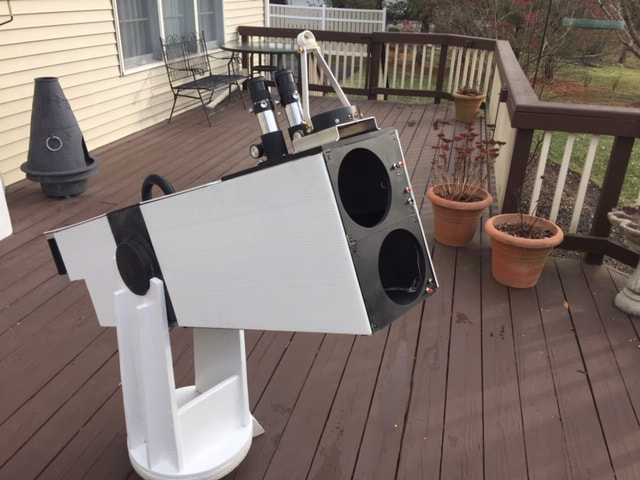
Build a 114mm, Dual Newtonian, Offset Stacked, Binoscope
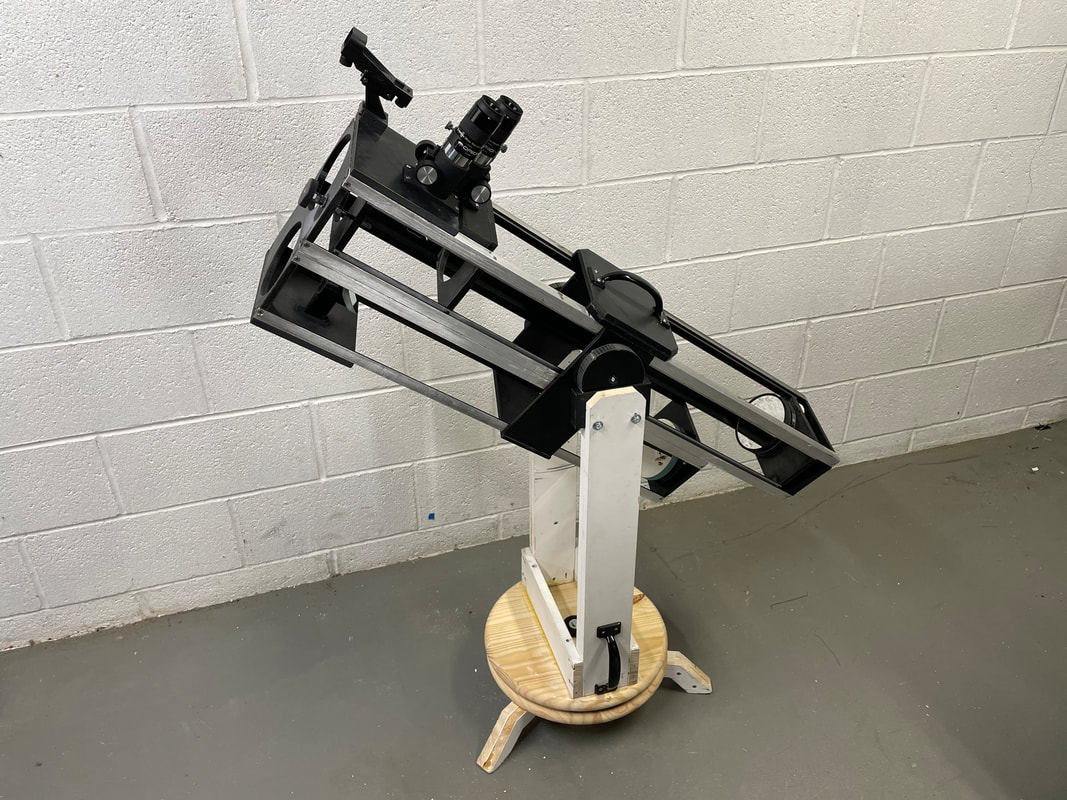
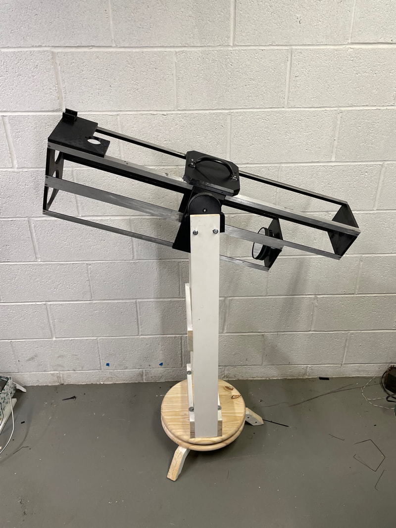
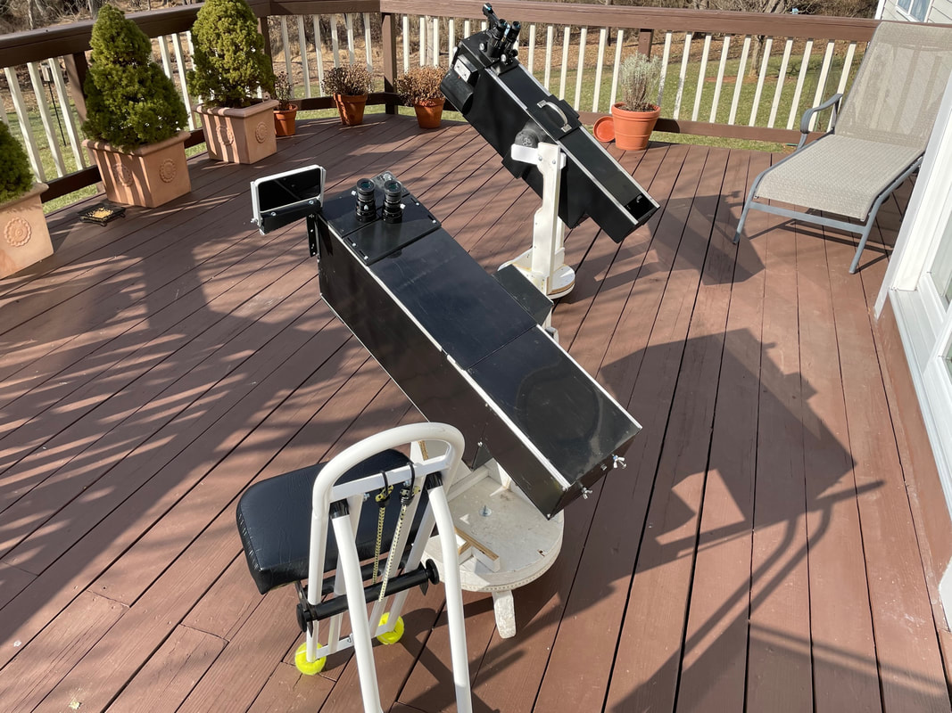
Shown above is a Dual Newtonian Binoscope (without light covers) that uses two 114mm F8 mirrors, Nearly all the parts can be made using a 3D printer and a step by step plan will be given that will enable it to be built by any average "do-it-yourselfer", with an interest in amateur astronomy. There are many designs for classic Newtonian telescopes that use 3D printing for creating the mechanical parts but to my knowledge this is the only complete set of plans for a "Dual Newtonian, Offset Stacked, Binoscope". The advent of the 3D printer, which creates accurate and reproducible parts, enables this design to be realized and shared.
The design of stacking two Newtonian telescopes was first suggested by Sir John Herschel but with no indication of how to adjust the inter pupillary distance (IPD) or a means of merging the images while viewing. This basic design was improved upon by Peter Wraight in 1990 and shown at the Texas Star Party where the features for varying the IPD and merging of the left and right images were all motorized. A further improvement was suggested and patented (#5416632, expired) by James H. Carlisle in 1995 for making the binoscope more comfortable to use when observing near the zenith. All these improvements have been combined and realized using 3D printing technology which enables a significant reduction in overall complexity and weight.
All the 3D .STL files are available for public download on tinkercad.com. To obtain access, sign up to Tinkercad and search for me, petertinkerer, (under the people heading), click on "petertinkerer" and look for all the "114mm Part#XX" files, where XX stands for 1 to 50. If you have trouble seeing the files drop me an email [email protected] . Tinkercad is a great CAD software package that is free and incredibly easy to use. So if you are budding ATMer with a 3D printer this binoscope will keep you busy for several weeks and give your 3D printer a good work out. All the 3D parts can be printed on a 200mm by 200 mm printing bed apart from the side bearings. These could easily be printed in two parts to keep the print size within a 190mm limit. I use a Creality CR-10 3D printer which has a 300mm*300mm glass print bed and I am very satisfied with the quality of the printed parts. I print directly on the glass plate and use Aquanet hair spay to ensure that there is good adhesion of the filament to the print bed. After the glass print bed has cooled the 3D part is simple to take off with no effort.
It will take some time to describe each detail of the build but to get started here are the lengths of aluminum angle that are needed:
The size of the aluminum angle is 3/4 inch by 3/4 inch by 1/8 inch thick
4 pieces 1020mm in length
4 pieces 900mm in length
4 pieces 770mm in length
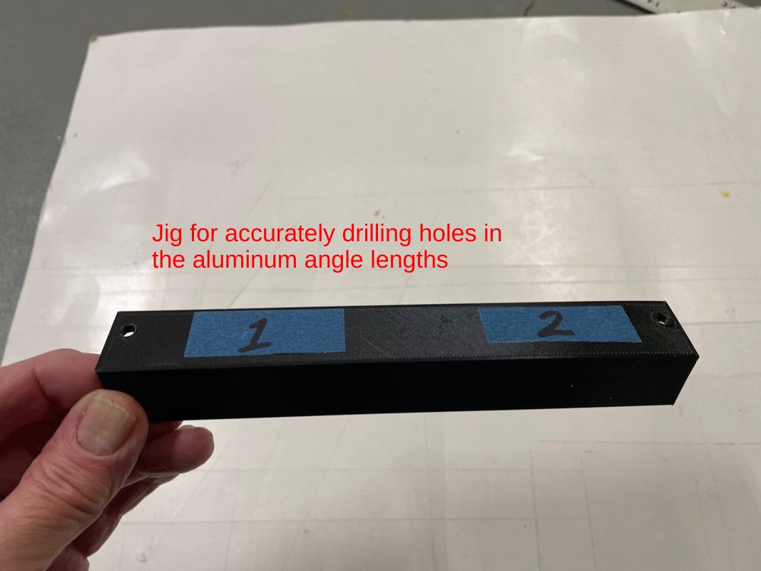
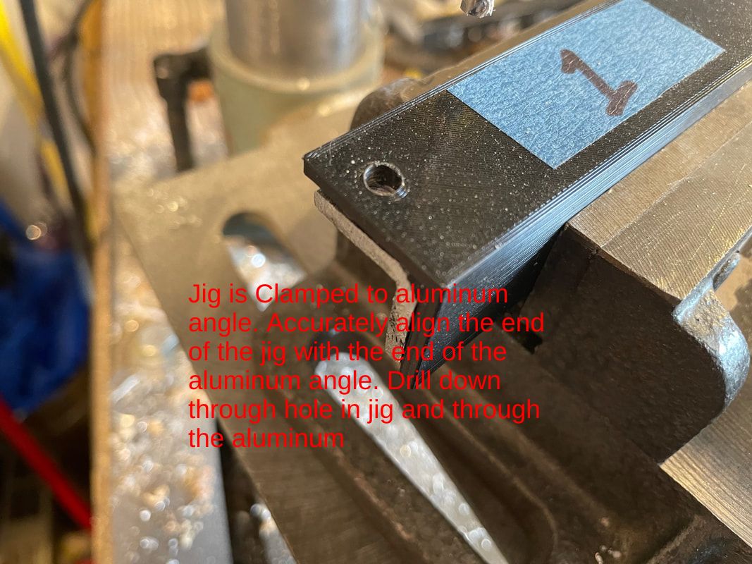
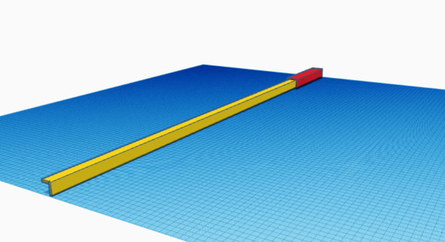
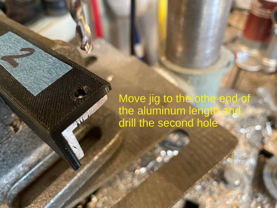
In order to drill the 11/64 inch (4.4mm) holes accurately in the aluminum angle download and print the file labelled "114mm Part#50 Binoscope" . This is a jig which is clamped over the aluminum angle to provide a guide for drilling the holes using a drillpress.
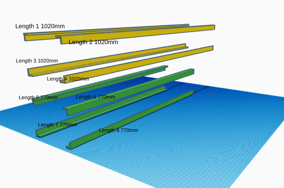
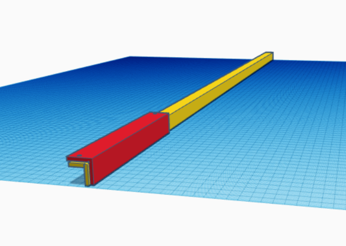
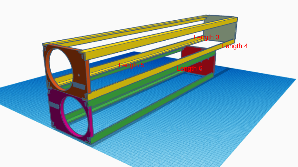
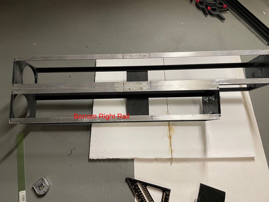
We are going to start by building up the main frame by preparing the 8 lengths of aluminum angle as shown below. Lengths 1-4 are 1020mm in length and lengths 5-8 are 770mm.
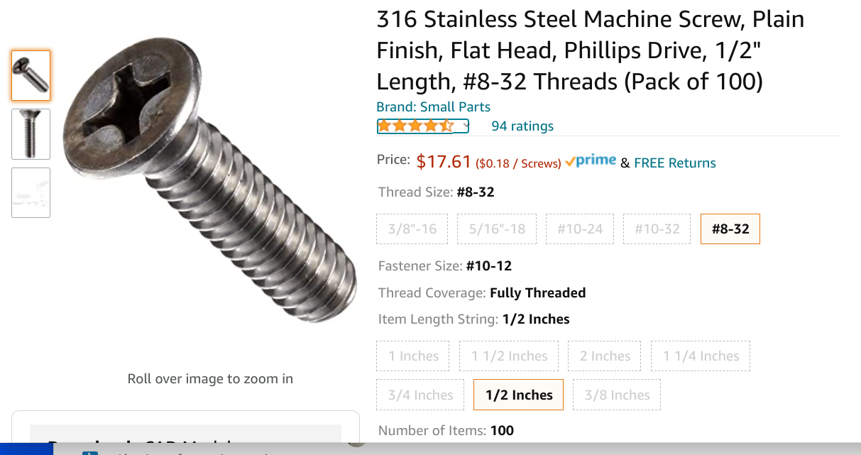
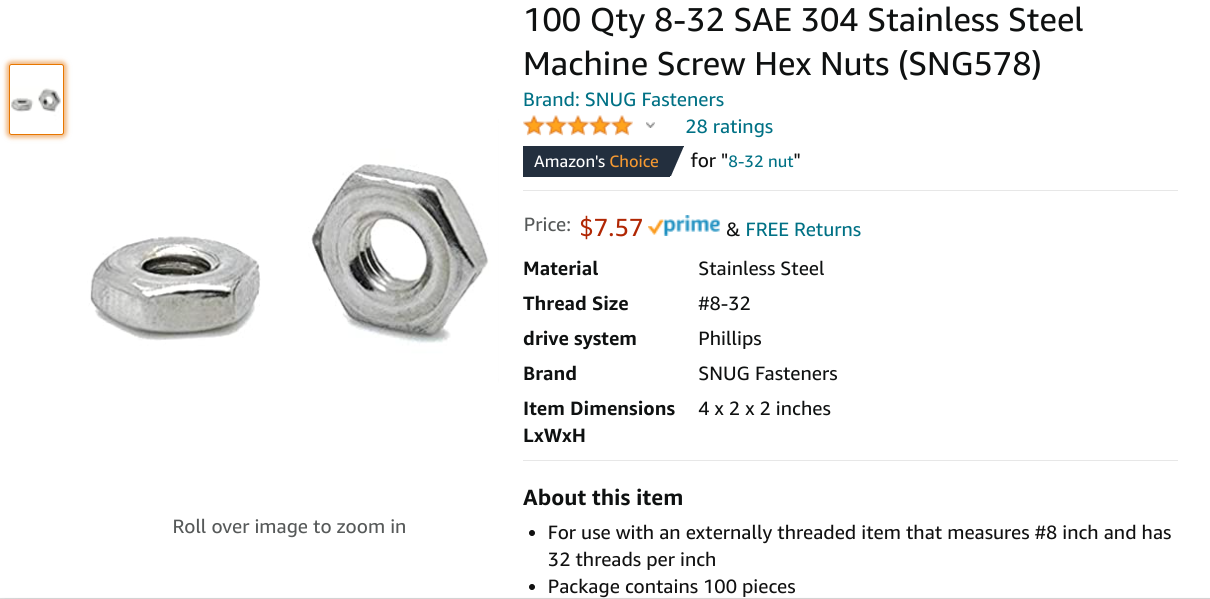
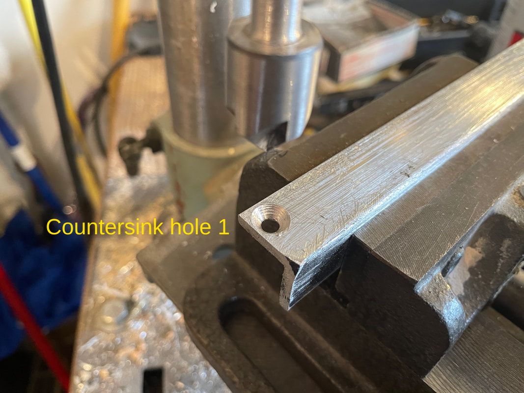
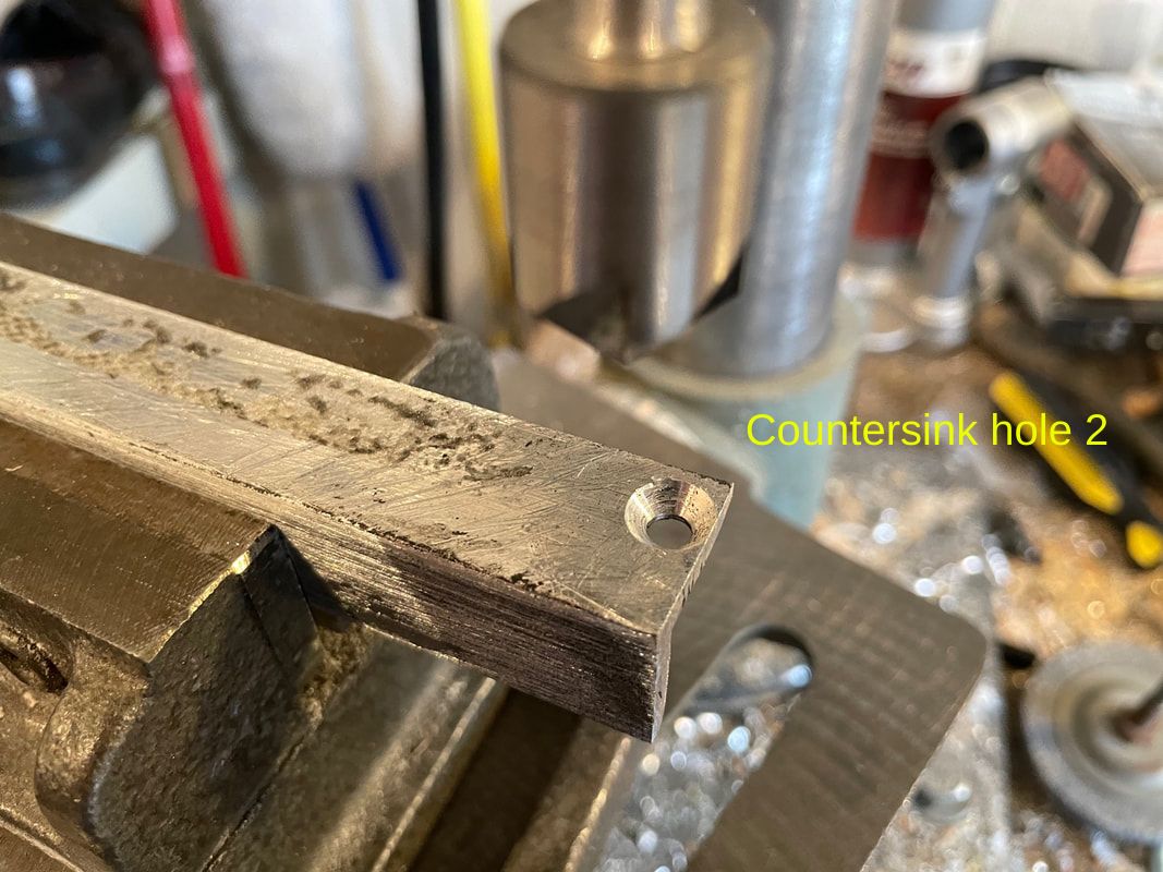
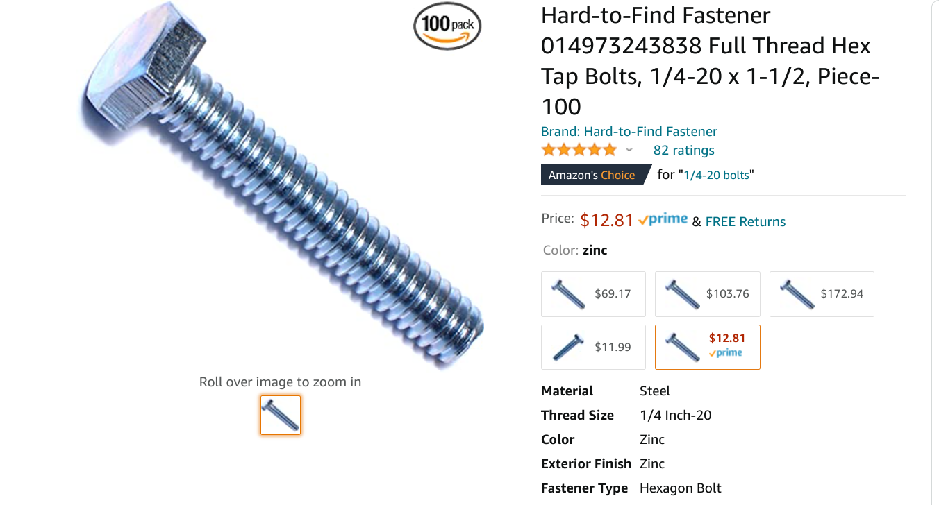
Next we are going to drill and countersink the 11/64 inch( 4.3mm) holes, 5mm from each end of the 8 lengths. The holes need to be positioned accurately and to help in this task you want to print out the jig (114mm Part#50 from Tinkercad, search under petertinkerer or directly for the printed part "114mm Part#50 Binoscope"). Countersunk 0.5" 8-32 nuts and bolts are used to fix the 3D printed parts to the aluminum lengths. Here are the Amazon pages to order these:
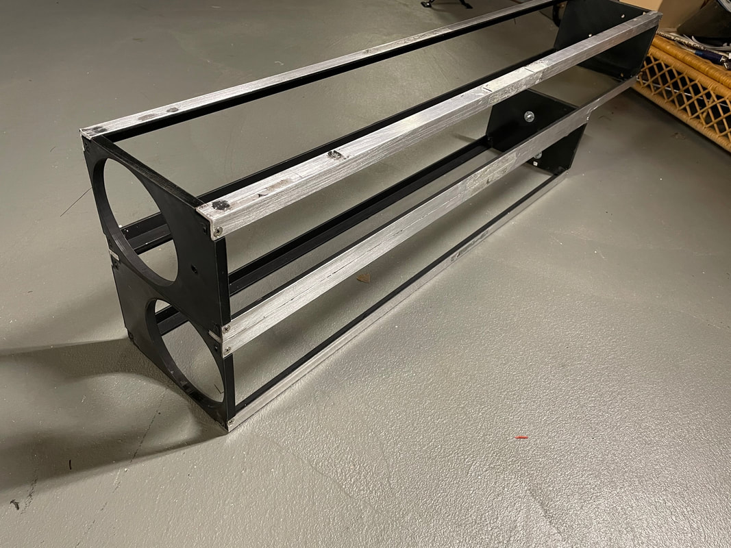
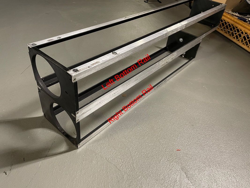
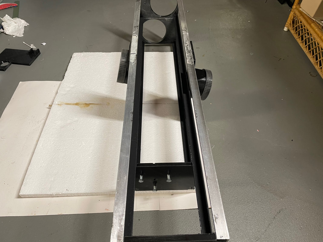
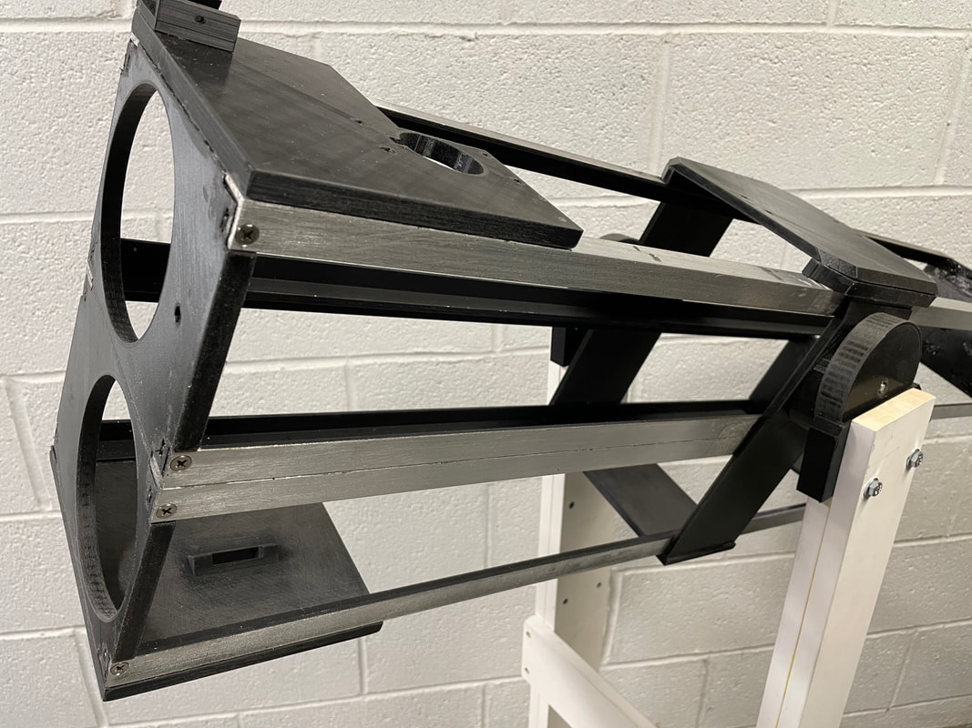
This is a view of the main frame that we are starting to build up and below is a photo of the actual unit. Note where all the drilled holes are. There are only two holes per aluminum length since they are only attached from the sides. You are now going to glue length 3 to length 5 and length 4 to length 6.
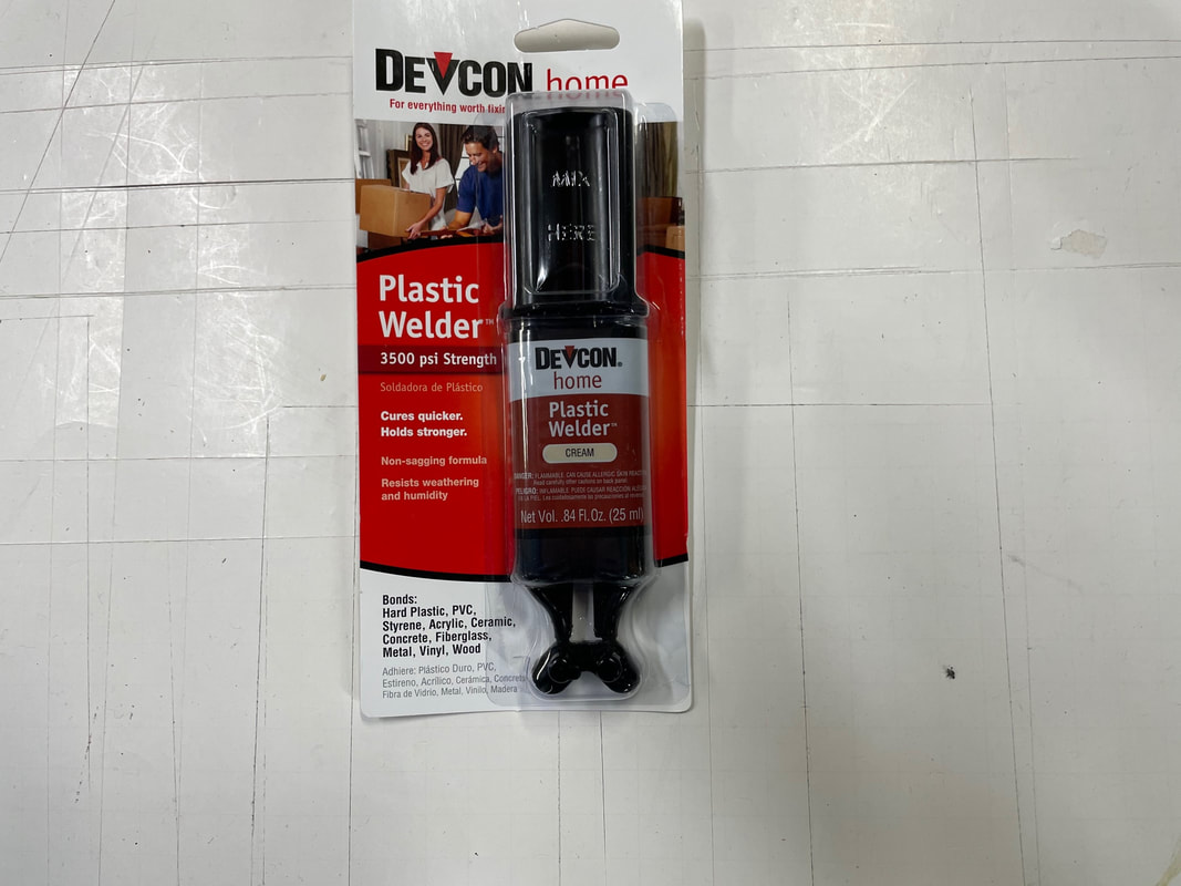
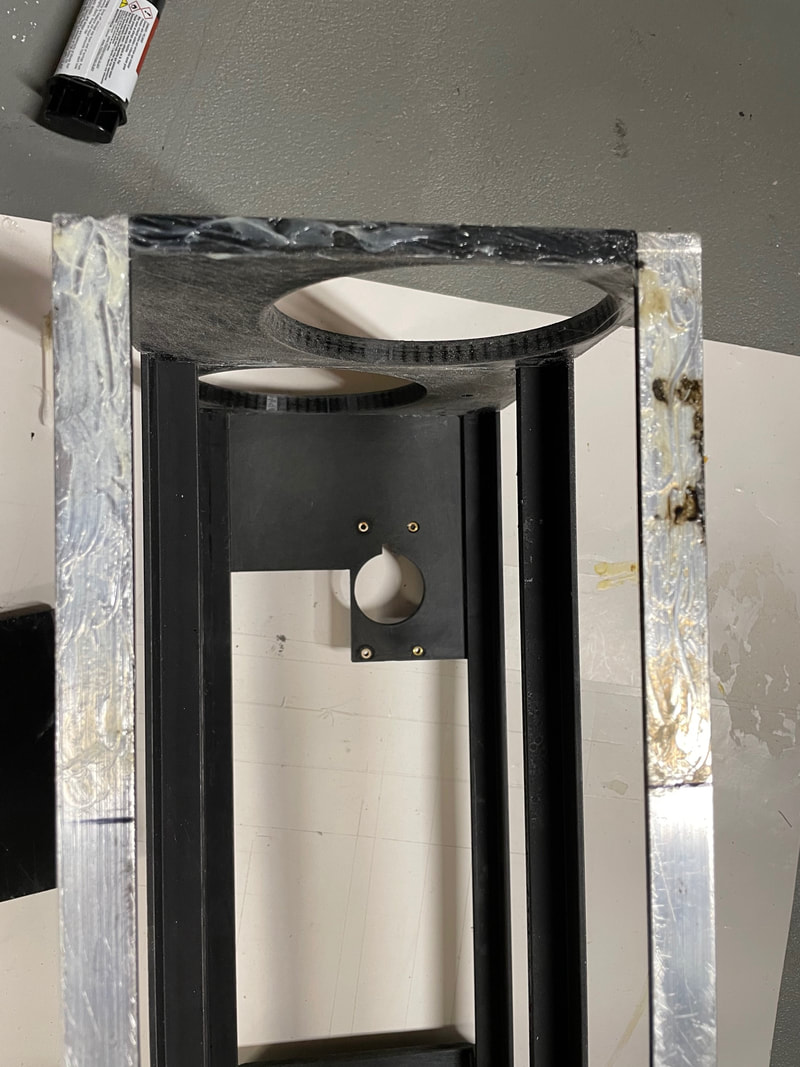
To glue aluminum length 4 to aluminum length 6 and aluminum length 3 to aluminum length 5, I use Devcon plastic welder and it works very well even for aluminum on aluminum. Before you glue the aluminum angle together you want to rub the mating surfaces with 100 grit sand paper and clean them with alcohol. The plastic welder is essential for gluing the 3D parts to the aluminum lengths which we will be doing later.
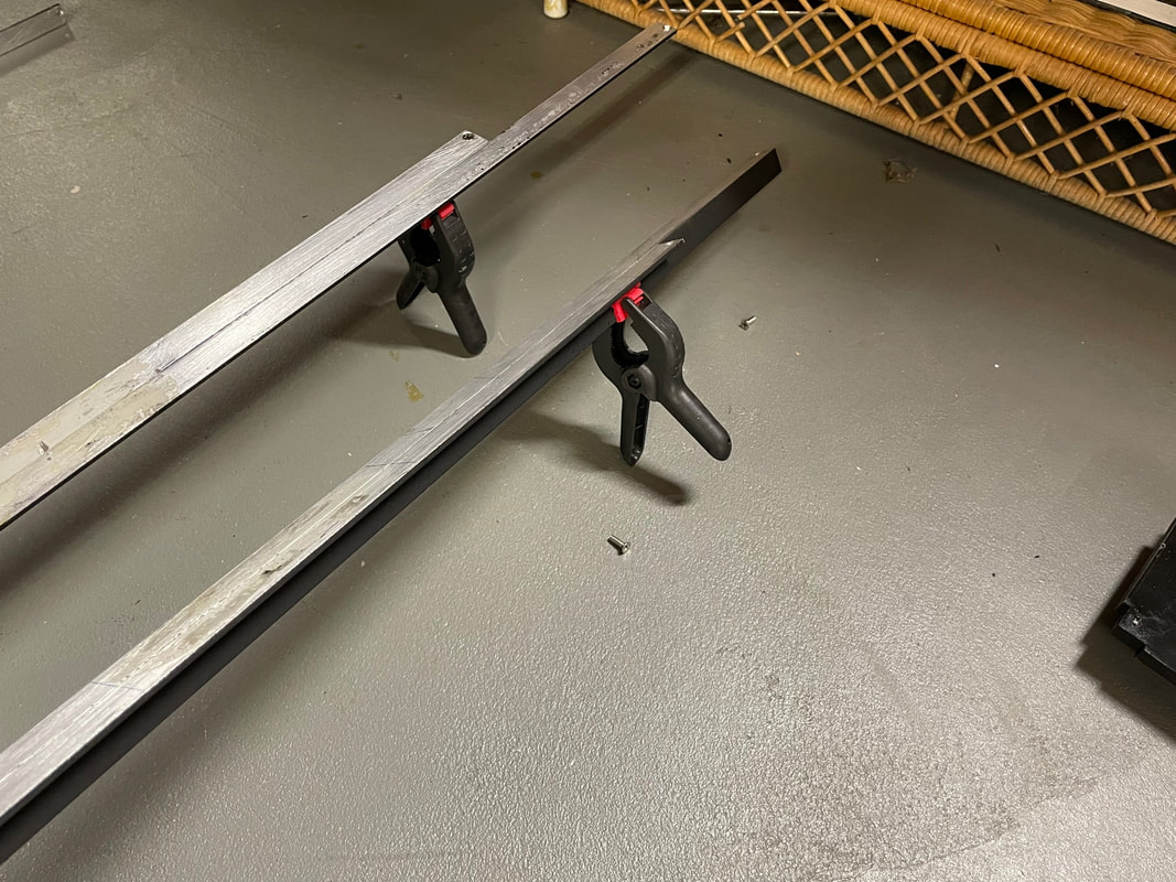
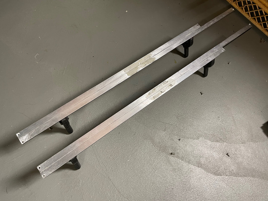
Here are the aluminum lengths 4 and 6 and 3 and 5 being glued together. You need to clamp them while the glue sets up (at least15 minutes). Make sure they are accurately aligned when you clamp the lengths together since you will only have a minute or two to make adjustements.
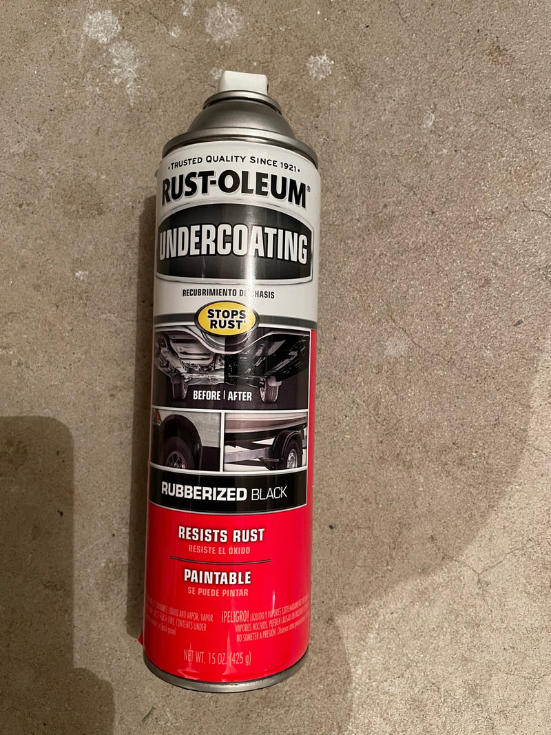
After you have drilled and countersunk all the holes in the aluminum lengths and glued length 4 to 6 and length 3 to 5 you are going to paint the inside angle of all the aluminum lengths making up the main frame. You can use any flat black paint that you feel gives you the least reflective surface. I have used Rustoleum undercoating with good success.
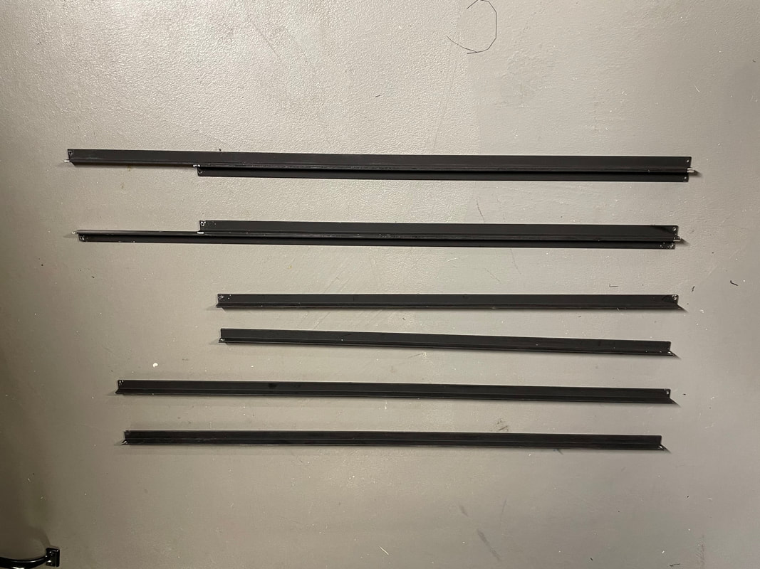
Here are the aluminum lengths of the main frame after they have been painted flat black.
Now its time to start 3D printing the two front plates and two rear plates of the main frame. Search on Tinkercad for:
114mm Part#7 Binoscope This is the upper front plate main frame
114mm Part#8 Binoscope This is the lower front plate main frame
114mm Part#12 Binoscope This is the upper rear plate main frame
114mm Part#13 Binoscope This is the lower rear plate main frame
After you have copied the .stl files use a slicing program to create the .gcode files for your 3D printer (I use Ultimaker Cura) no support is needed for these first 4 parts. Printing on glass and using Aquanet hair spray works extremely well. The part adheres very well while printing and releases easily once the glass bed has cooled.
I use black PLA 1.75mm filament from Hatchbox and 10% infill for these parts and found that the stability and accuracy of the parts is fine. If you were to leave the binoscope in the sun and in a hot car then there maybe issues with the PLA softening, but the parts are simple and everything is held in place by being screwed and glued to the aluminum lengths so it should be fine. If you want to use the higher temperature rated PETG then by all means go ahead and use this material.
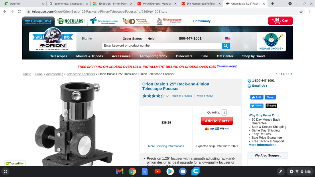
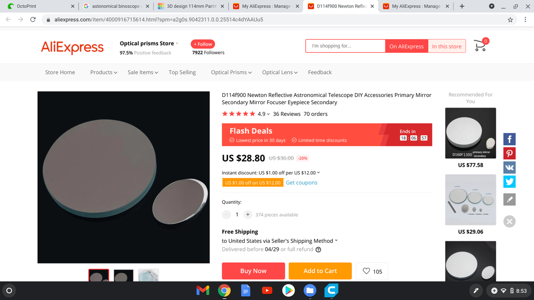
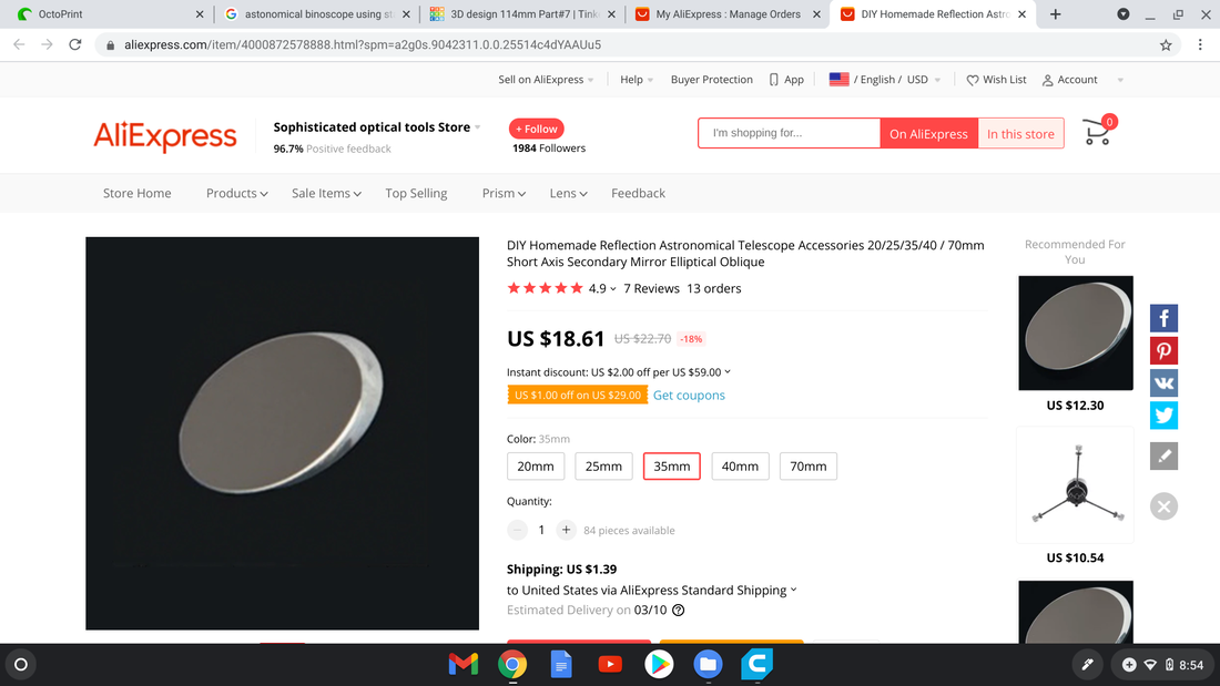
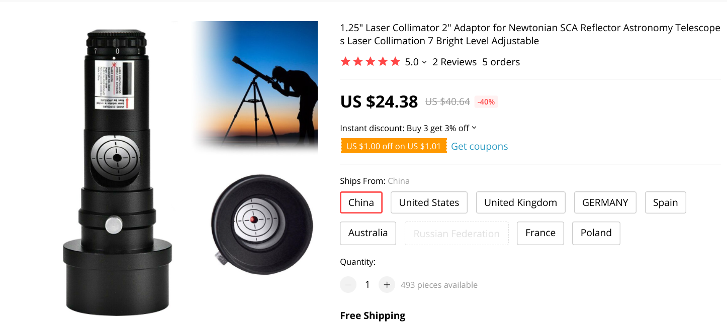
Now that you are starting to print the 3D parts it would be good to order the long lead time optical items. Here are screen shots that should be sufficient to enable you to order two focusers, two 114mm mirrors, one 35mm upper secondary mirror and one 40mm lower secondary mirror and a laser collimator:
Here are some other nut, bolts, washers you will need to order. You obviously will not need 100 1.25 inch 1/4-20 hex bolts and can probably find what you need at you local hardware store. Number needed is 12,
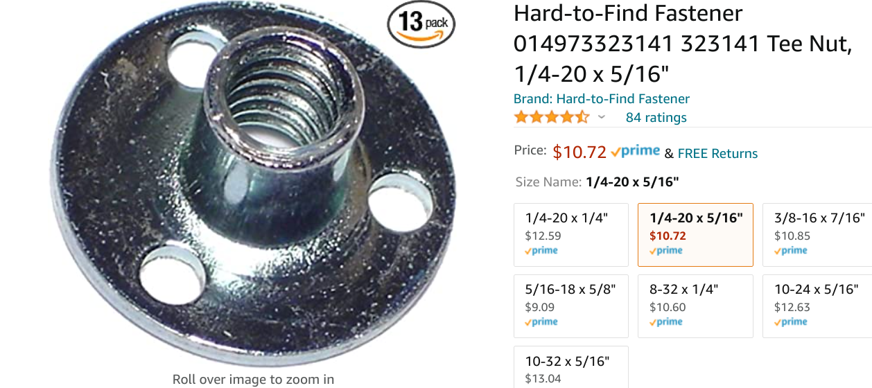
Here are the T nuts you will need (9 required):
You will need 1/4-20 nuts and washers.
Now let's prepare part#7:
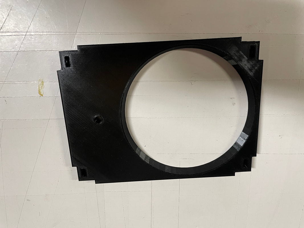
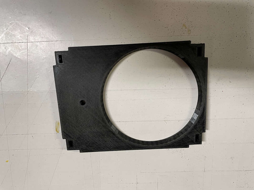
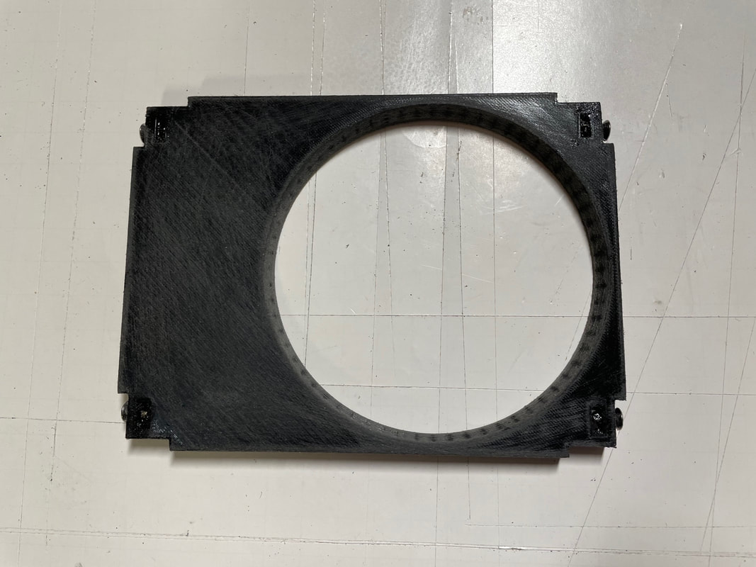
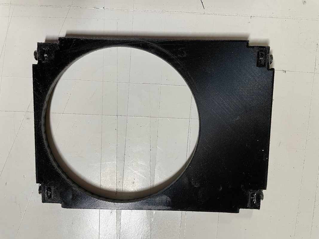
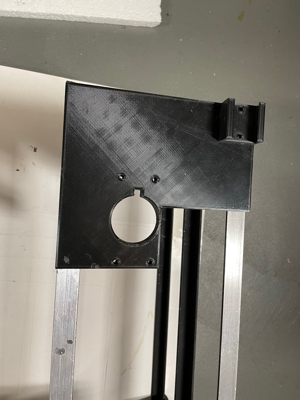
First you want to clean up the part with a file and 100 grit sandpaper. The aperture opens up from 115mm at the front to 120mm at the back. Take the shine off the PLA on the inside of the aperture and on the back.
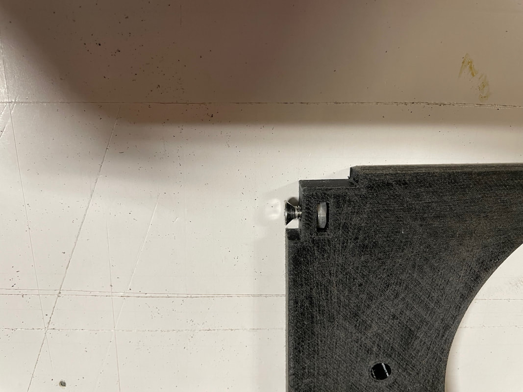
Next install an 8-32 nut in one of the side slots and loosely hold it in place with a countersunk 0.5" 8-32 bolt:
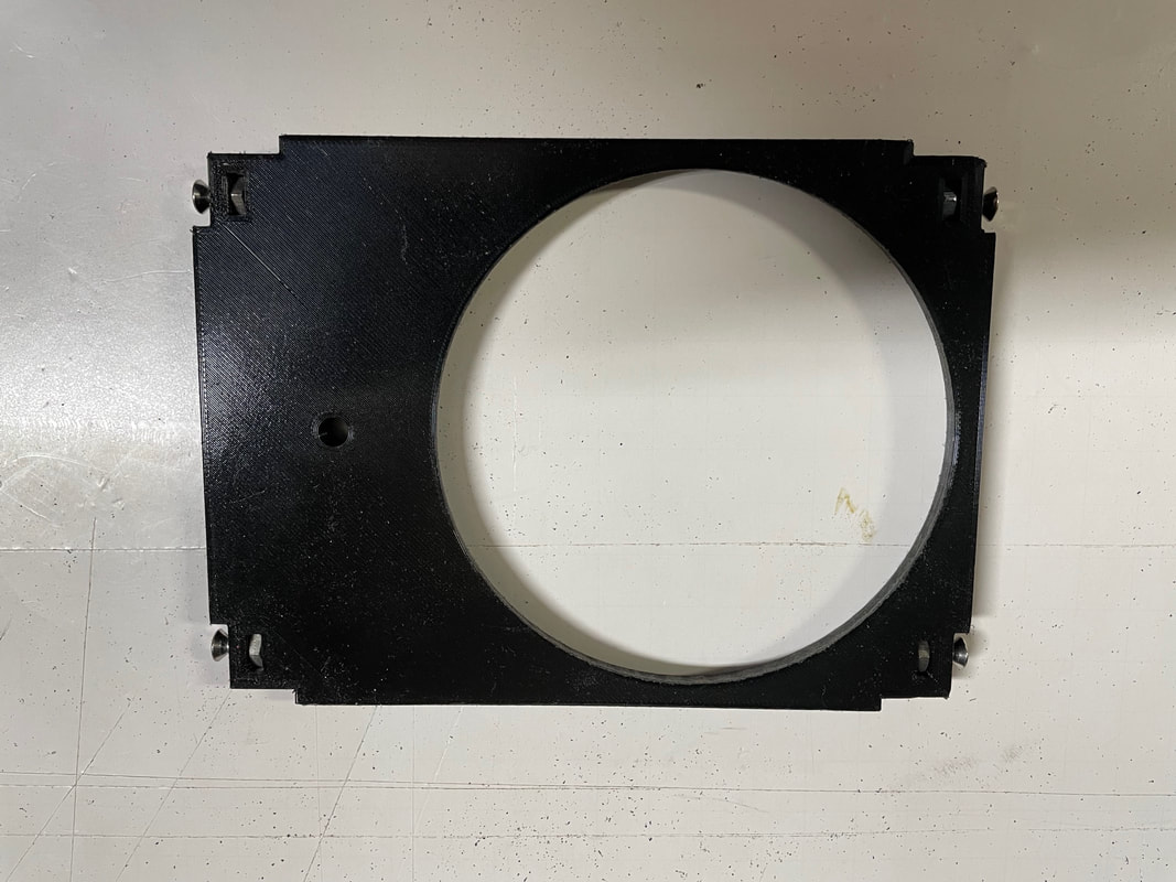
Repeat with the other 3 side slots:
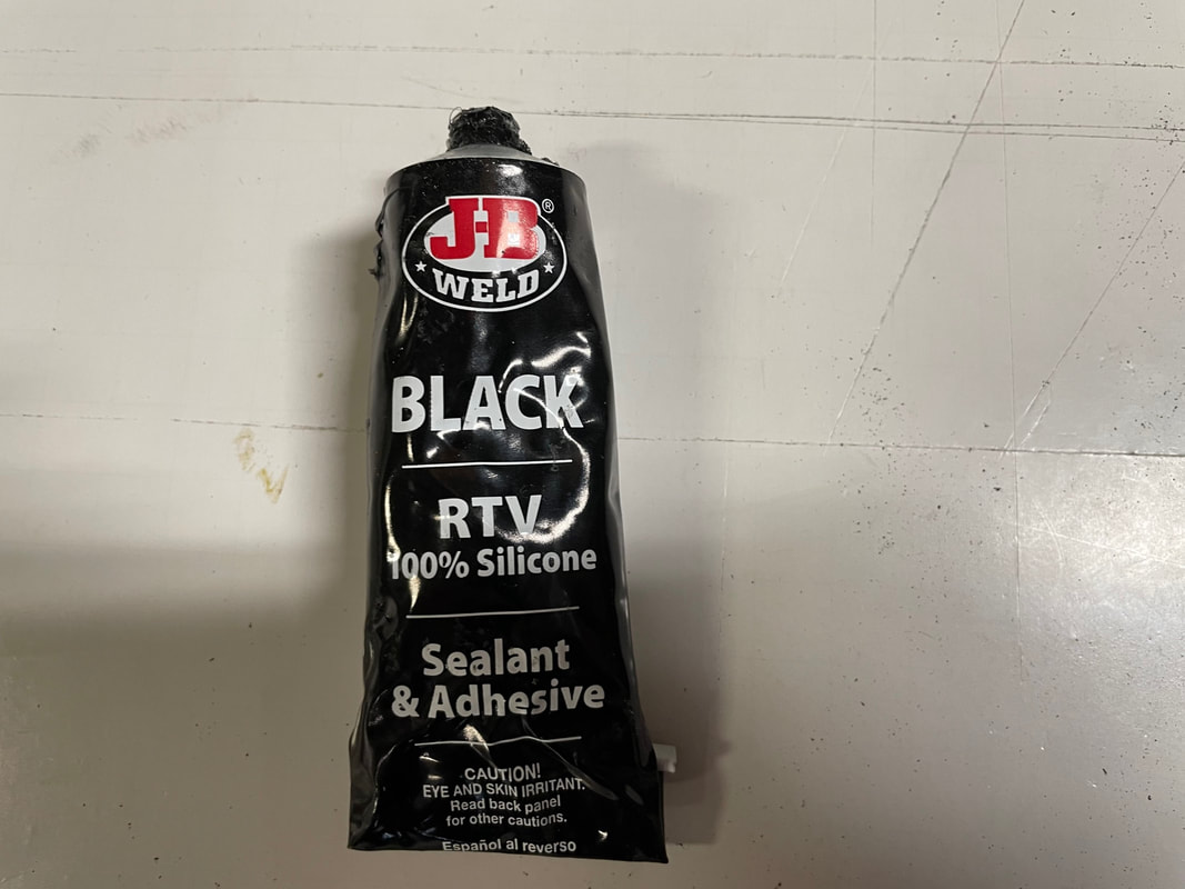
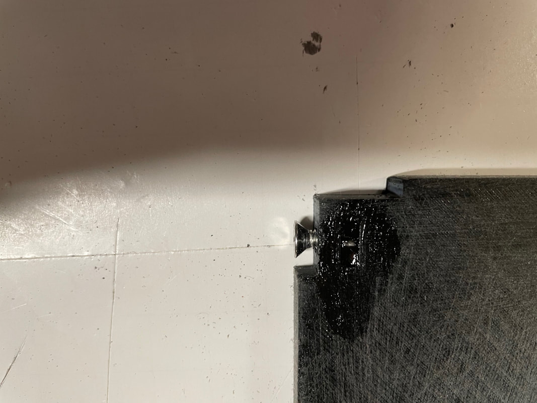
Using black RTV silicone you are going to put a small dab on each nut to hold them in place:
Now do the same set of procedures with part#8:
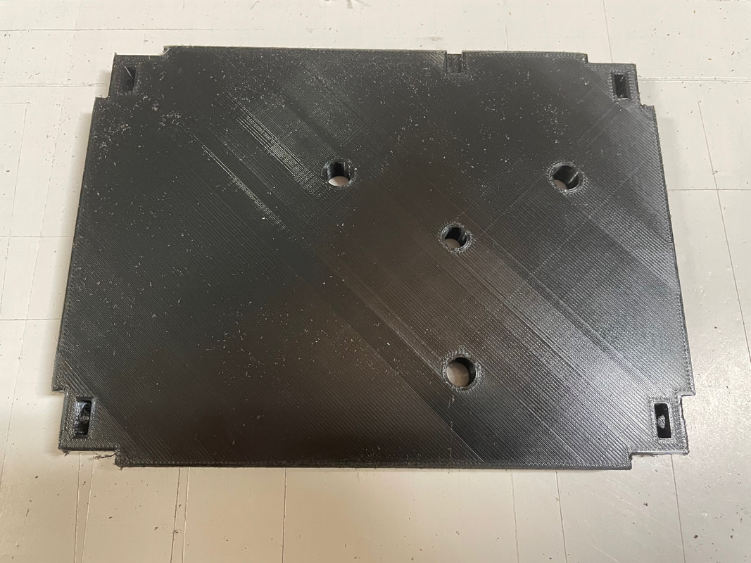
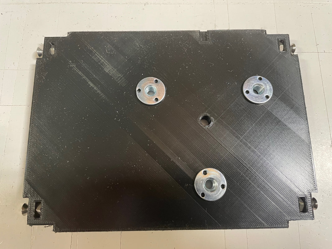
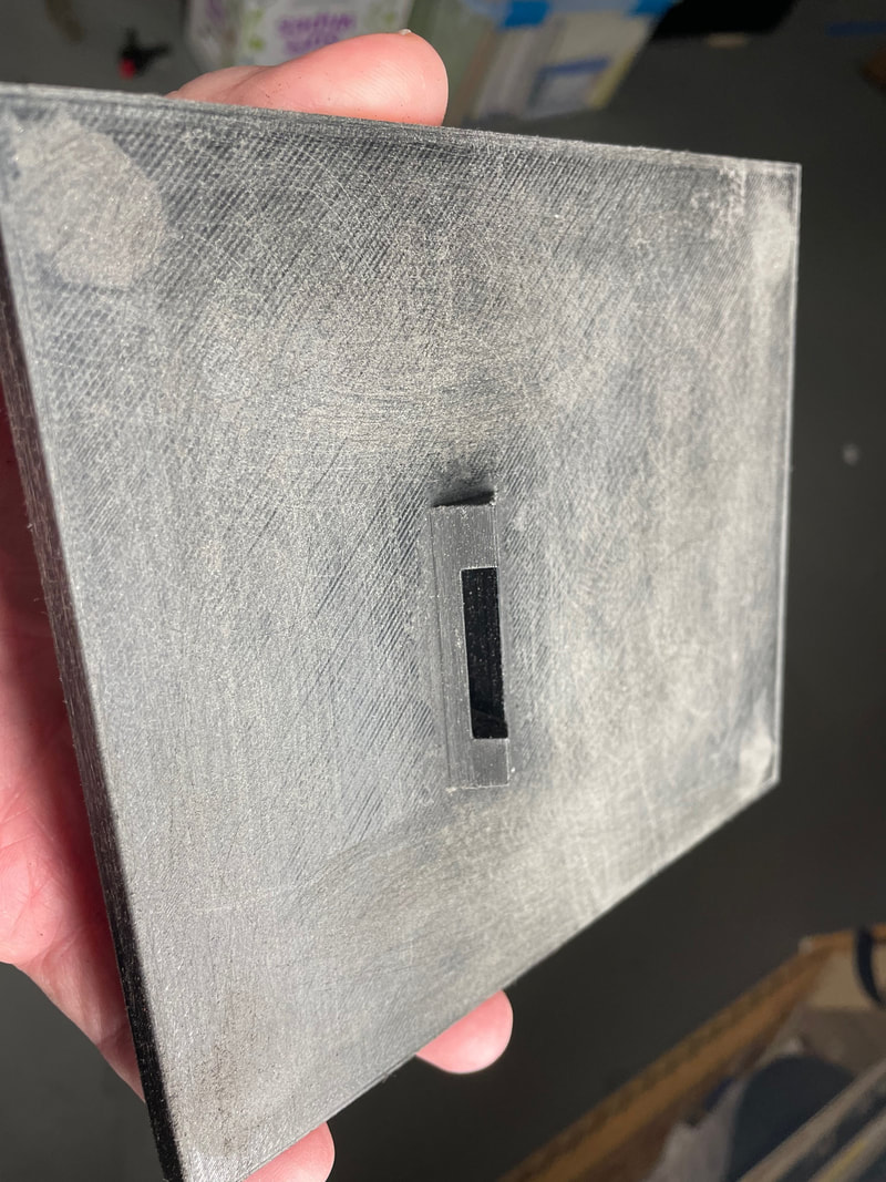
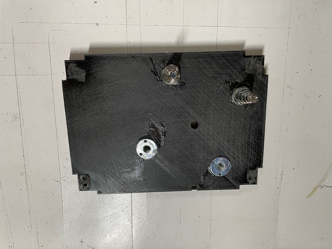
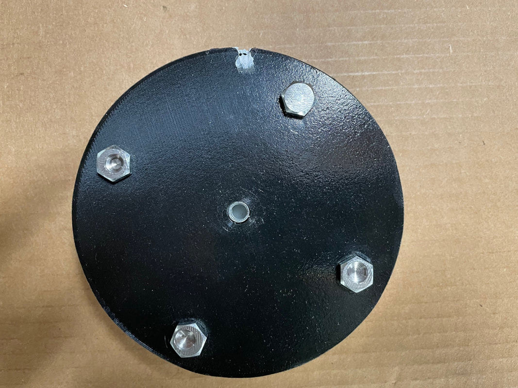
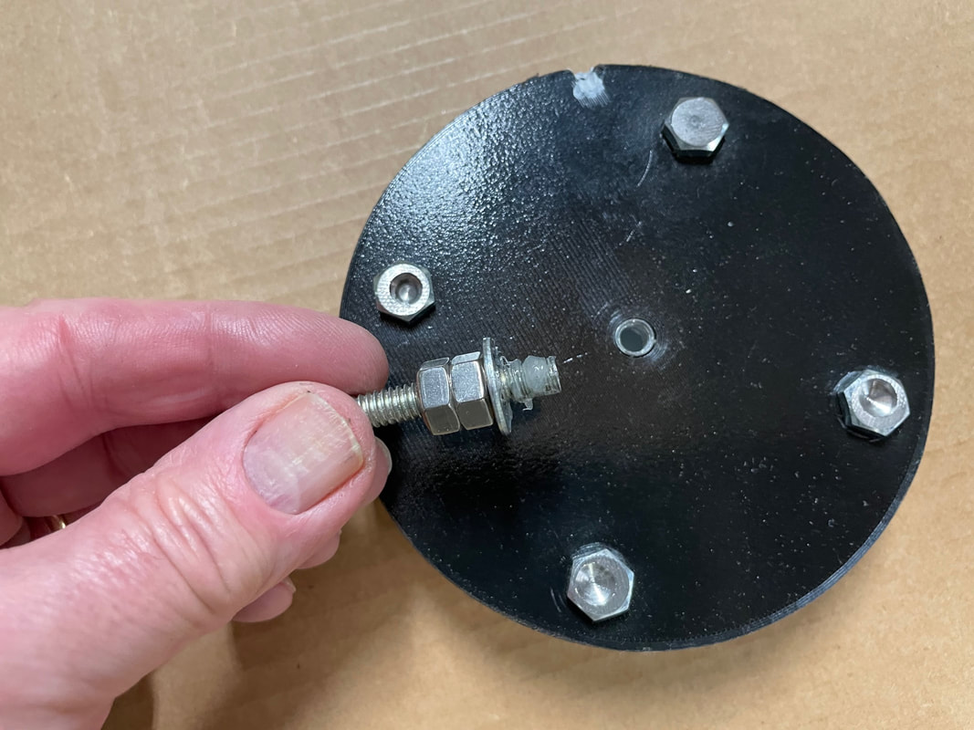
Next prepare part#12 and part#13. Part#12 is straight forward and all you need to do is to install 4, 8-32 bolts in the corners. For part#13 you install 4, 8-32 bolts and 3, 1/4-20 T nuts. Below is part#13, note the indent on the top, right. You will need to use this to orientate the part.
Next install the 3, 1/4-20 T nuts with the two part epoxy plastic welder. Install the 8-32 nuts in the slots in the corners and use the black RTV to fix these nuts in place
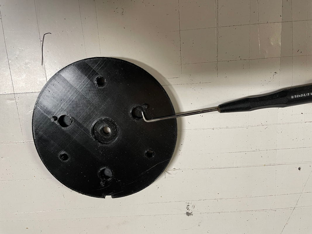
Next we will prepare the lower mirror mount part#20. Using a suitable tool make sure that the undercut groove in the 3 mirror gluing holes are free of PLA strings.
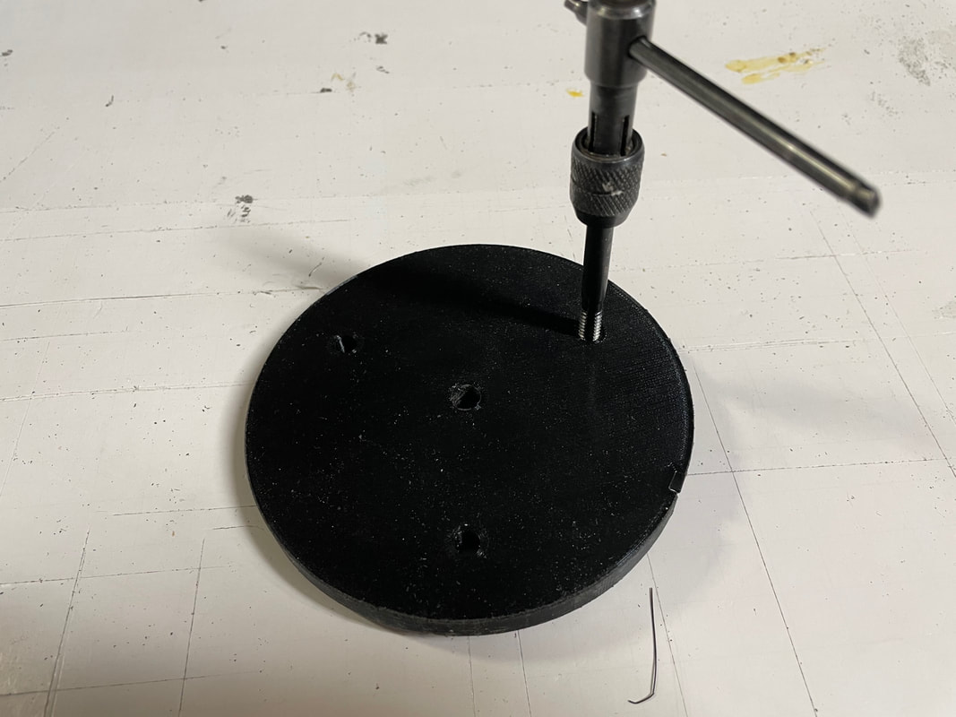
Tap the 3 holes for the mirror adjusting pads with a 1/4-20 tap
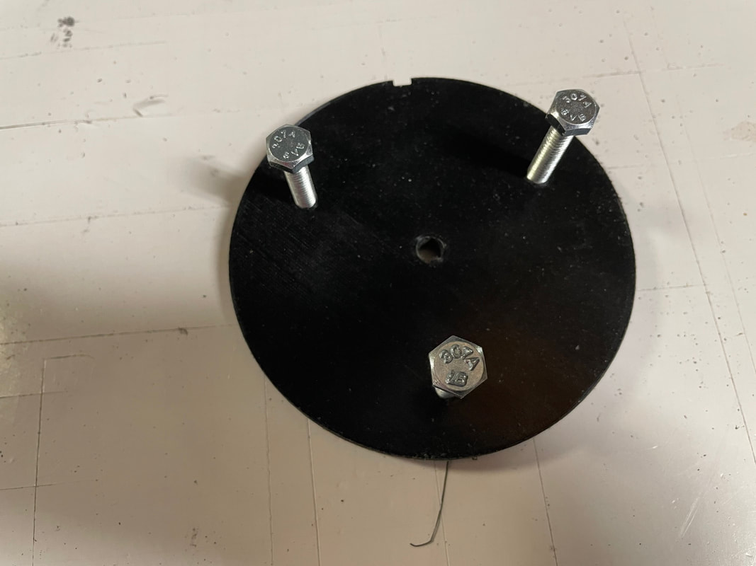
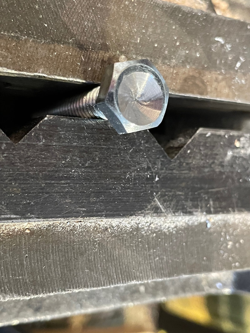
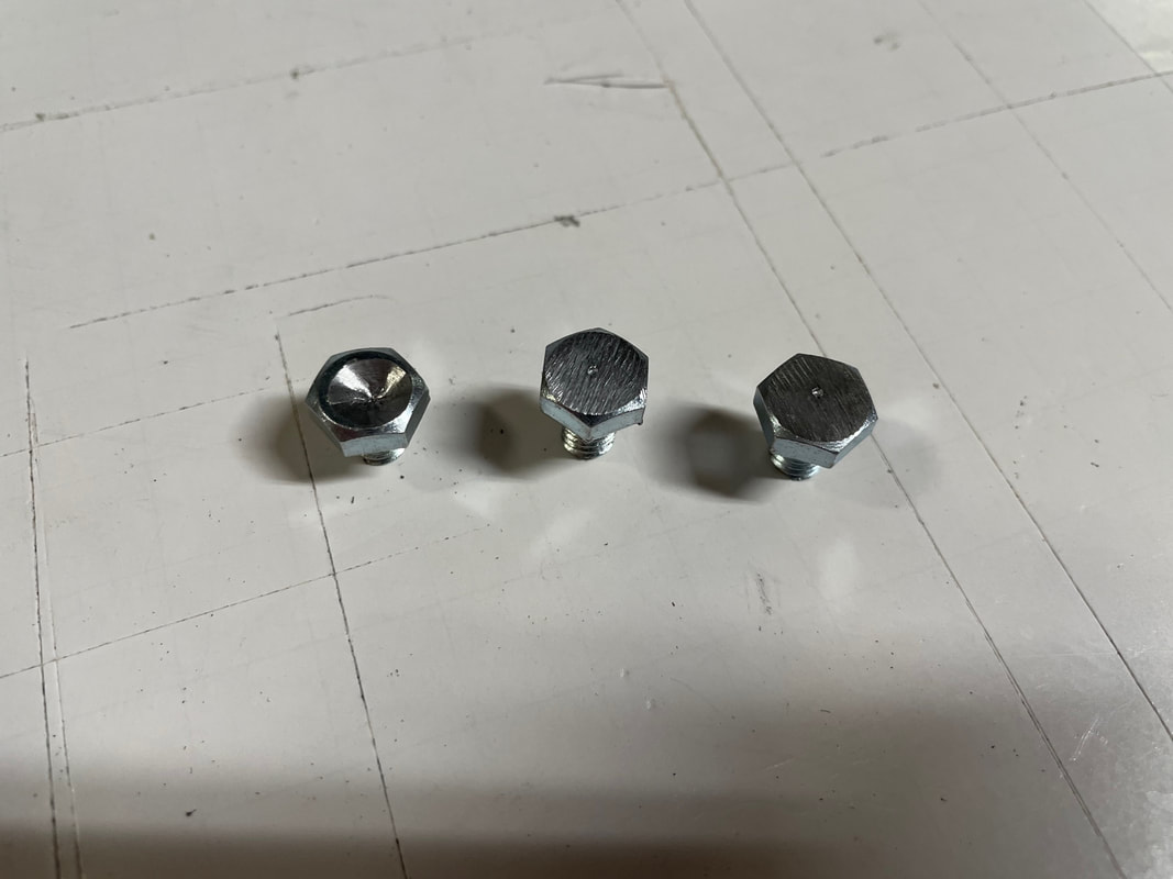
Take 3 of the 1.5 inch 1/4-20 hex bolts and check they can easily screw through the tapped holes. You are going to cut these down to 8mm in length. But first you are going to center punch one of the bolts, see below:
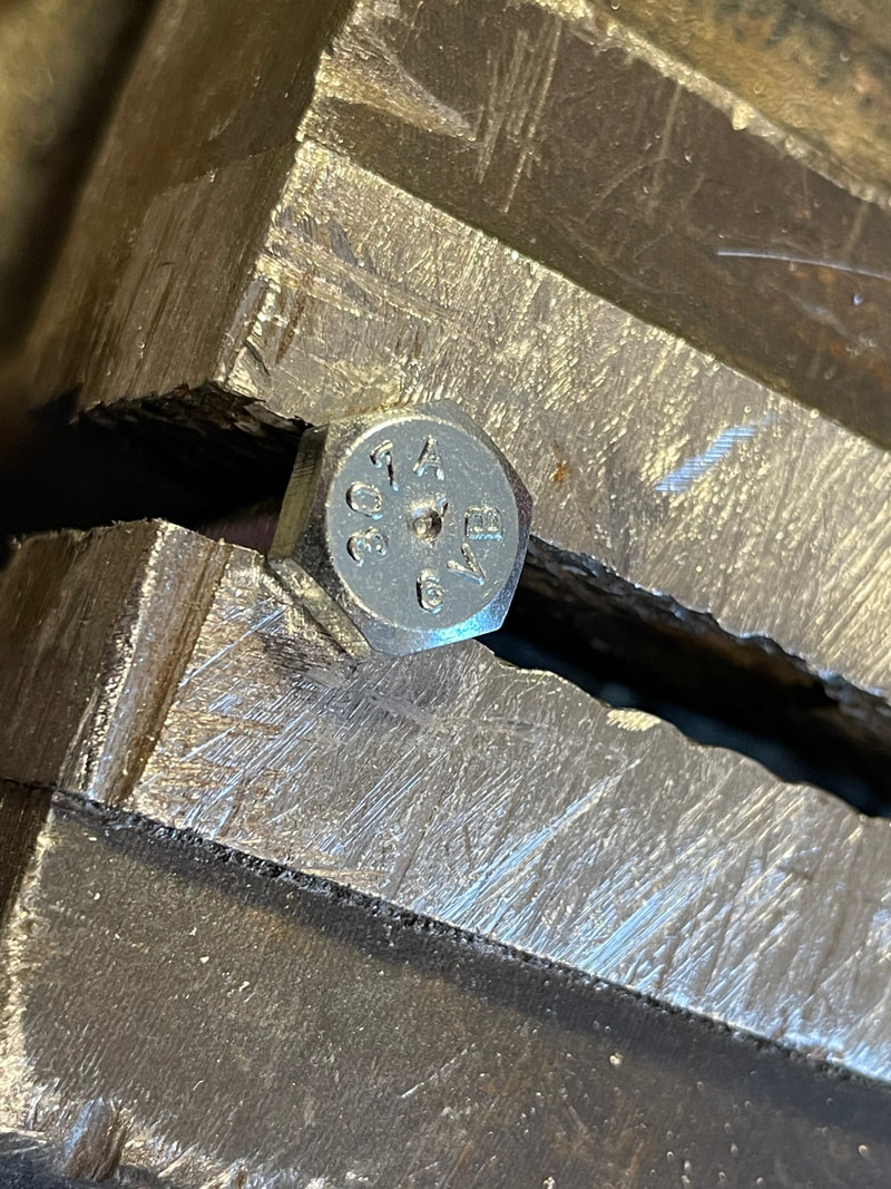
Center punch one of the bolts:
Next take a 3/8" drill to countersink the center as shown below:
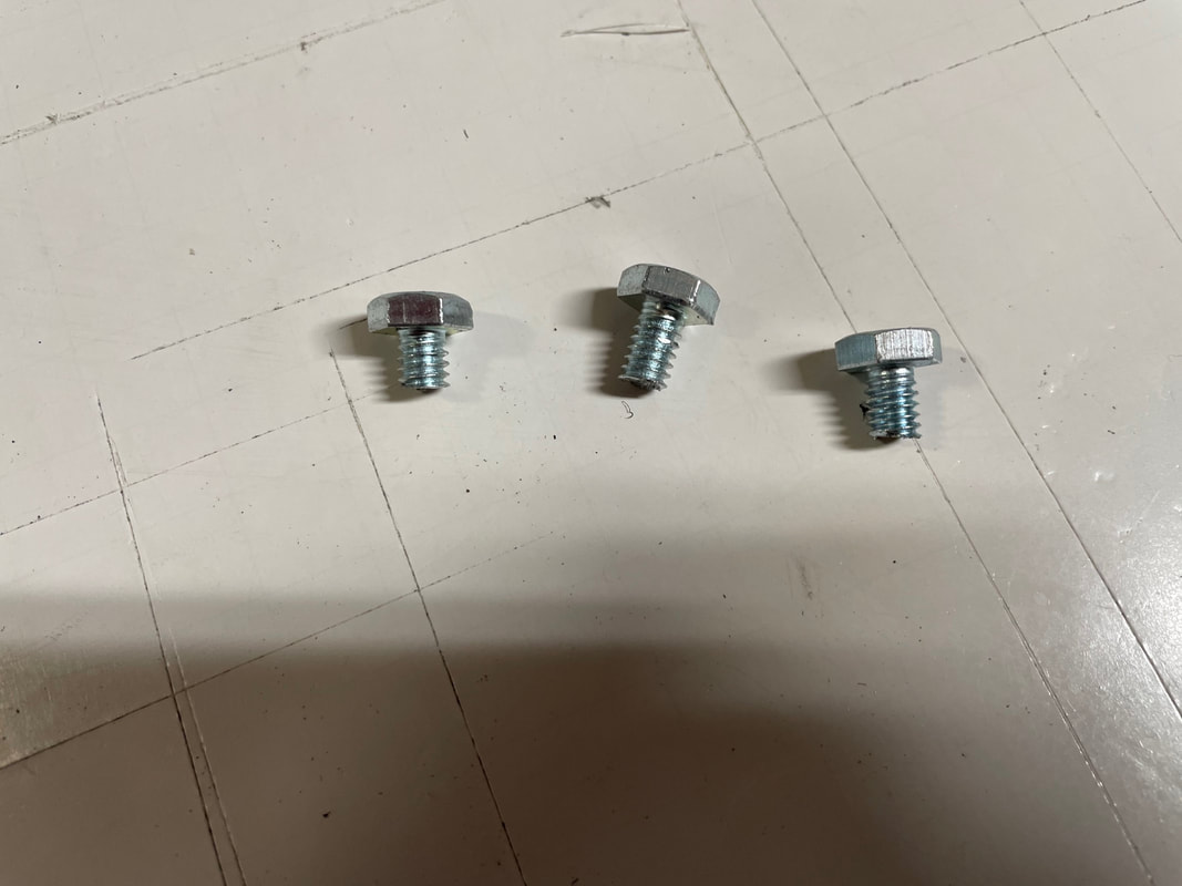
Cut the bolts down to 8mm in length and file the top of the other two bolts flat:
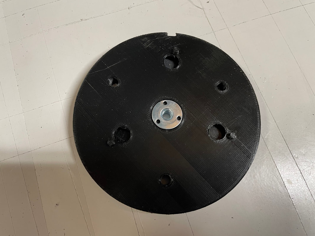
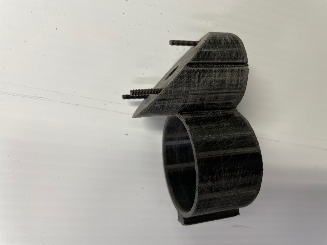
Take part#20 and glue in a 1/4-20 T nut as shown:
Screw in the 3, 8mm long, hex bolts from the back side. Use a little glue on the threads so they can never come loose:
Cut a 70mm long piece of 1/4-20 threaded rod and screw this in from the back until it is flush with the front of the T nut:
Put a small amount of glue on to the end of the threaded rod so that it will never come loose from the T nut. Do not over tighten the 1/4-20 nut when you lock the threaded rod into the T nut or you could compress the PLA. Just tighten it enough to hold it securely in place. When the glue sets up it will be very firmly held.
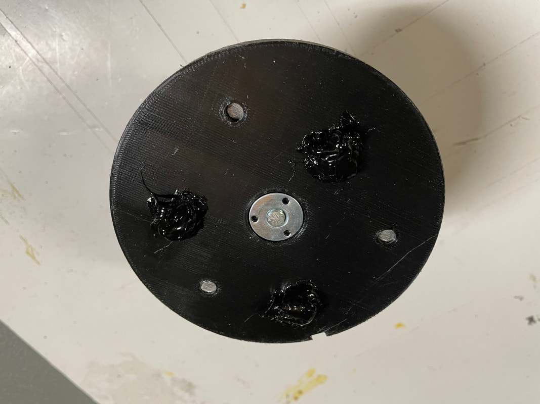
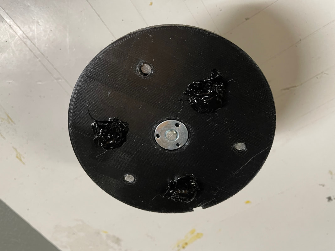
Now we are going to glue one of the primary 114mm mirrors to part#20 with black RTV silicone. Start by filling up the pad fixing holes making sure that the silicone goes inro the under cut groove.
When you are sure that the silicone is filling the pad, place another blob on to each pad area. You want to have sufficient so that when you place the mirror on top of the small stand offs the blob of silicone will flatten out to about a 20mm diameter circle.
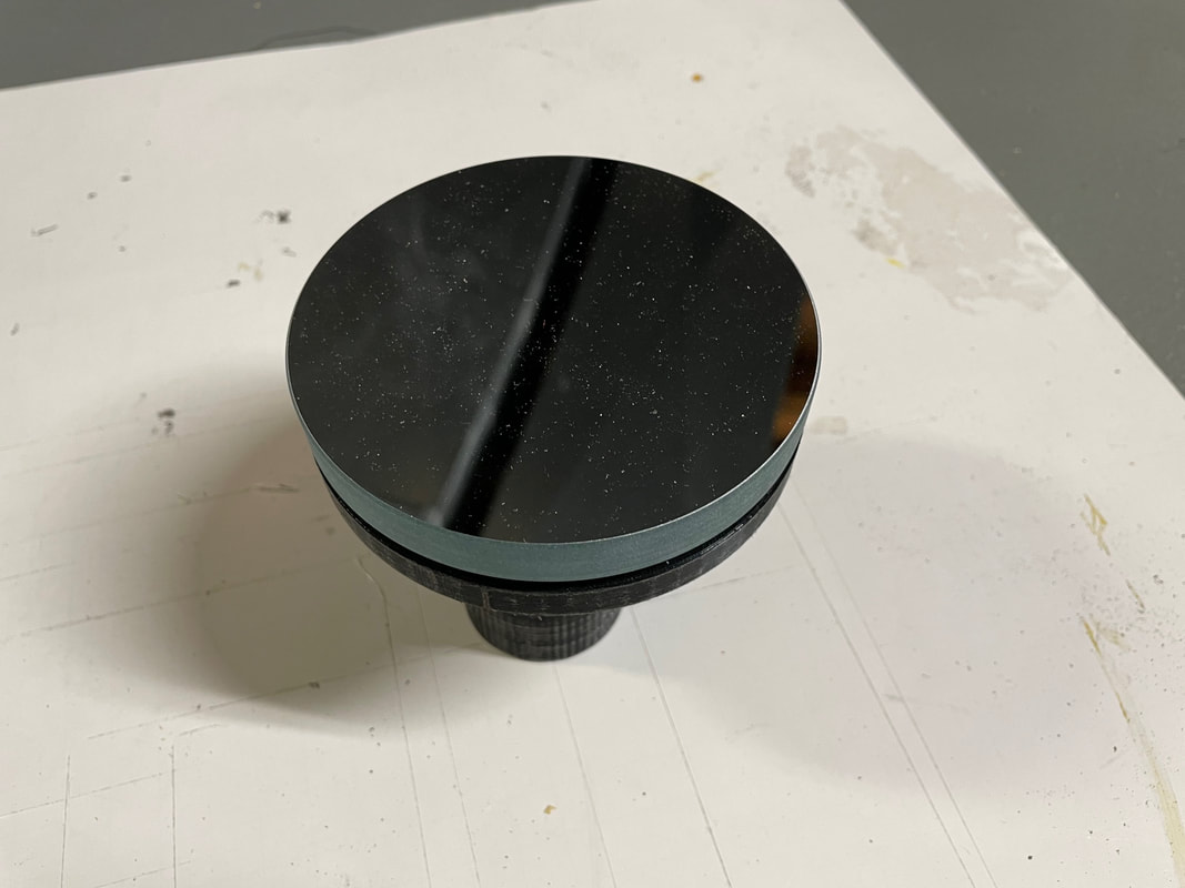
Place part#20, with the protruding 1/4-20 rod, on a suitable stand, such as a thick tube or jar, so that it stands up vertically with no chance of tipping over. Using cloth gloves, place the mirror gently on to the stand offs and exactly centered with part#20. You should feel the silicone spread out as the mirror comes into contact with the stand offs. Leave the assembly in a safe place for at least 24 hours before moving it to allow the silicone to set up.
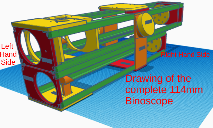
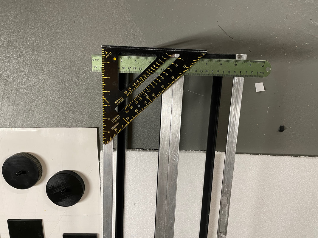
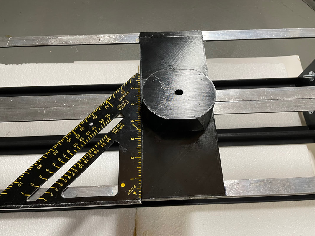
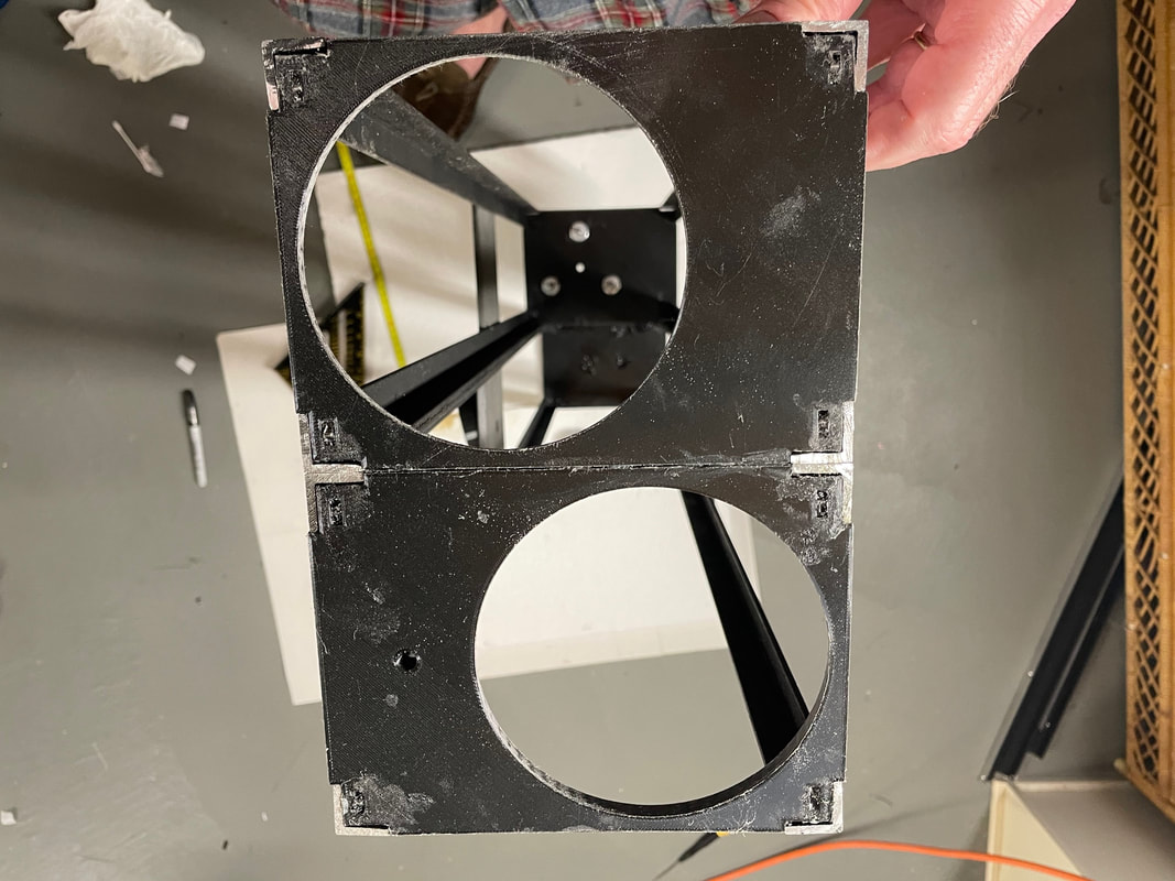
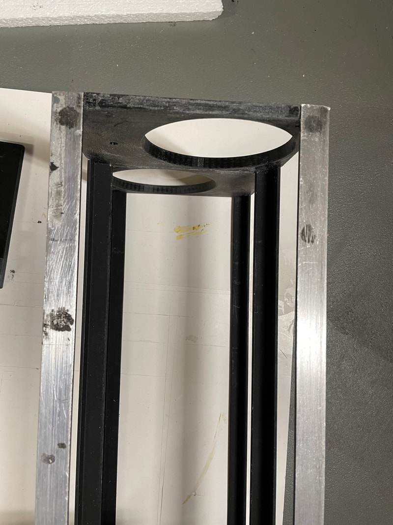
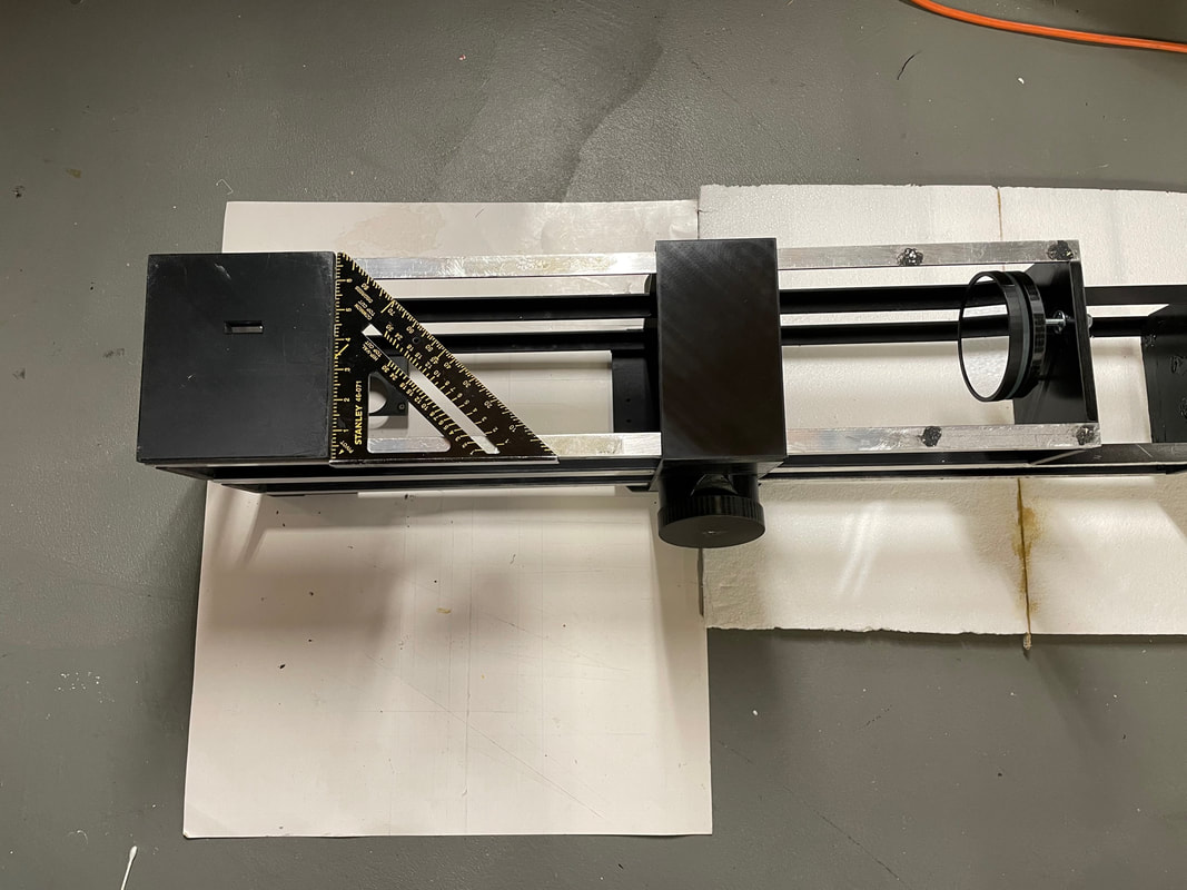
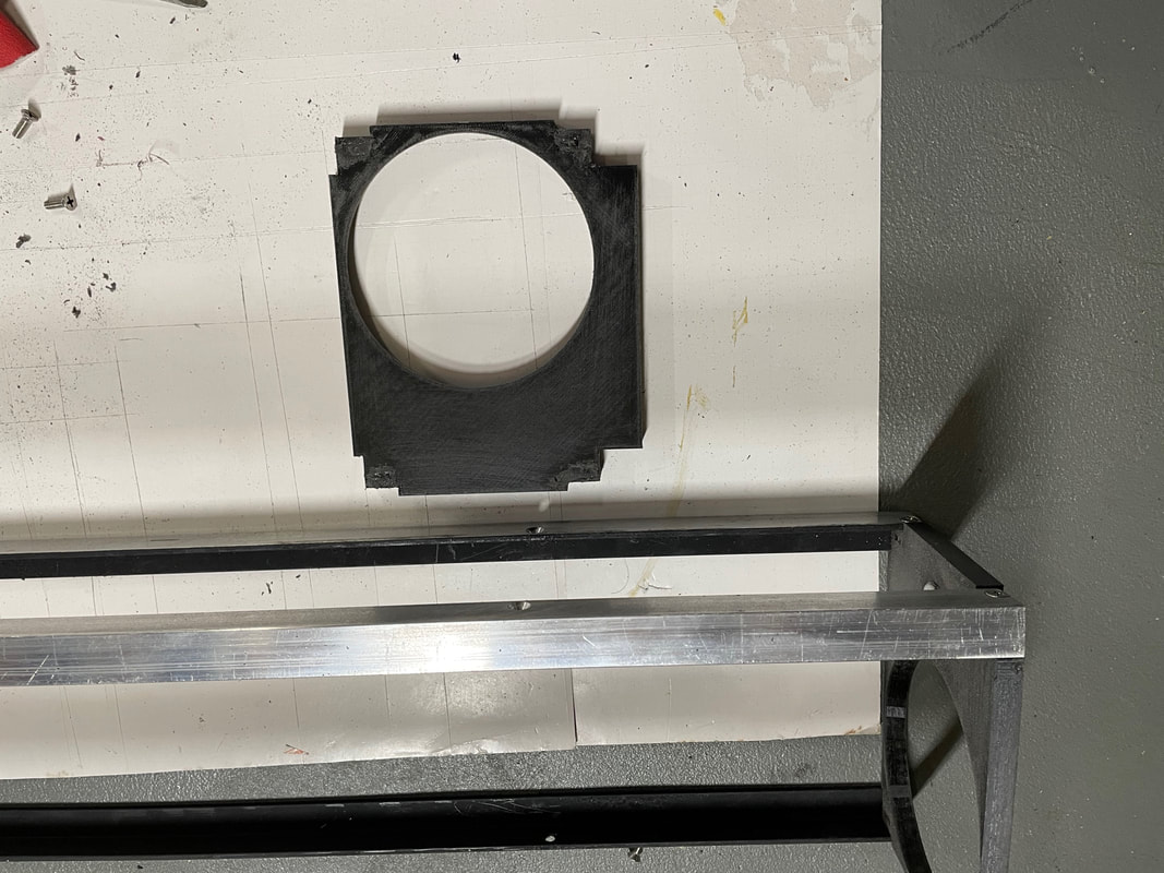
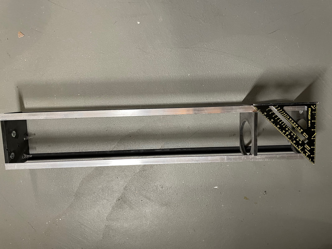
Assemble the main frame using the prepared aluminum lengths, and parts# 7, 8, 12, and 13. Before gluing part 14 to the left side (looking from the front of the binoscope) you need to be absolutely sure that the frame is square. Use a set square and straight edge to do this. Make sure you have the parts#7 & 8 the correct way round, i.e., the 115mm opening is at the front and the 120mm opening faces back into the frame.
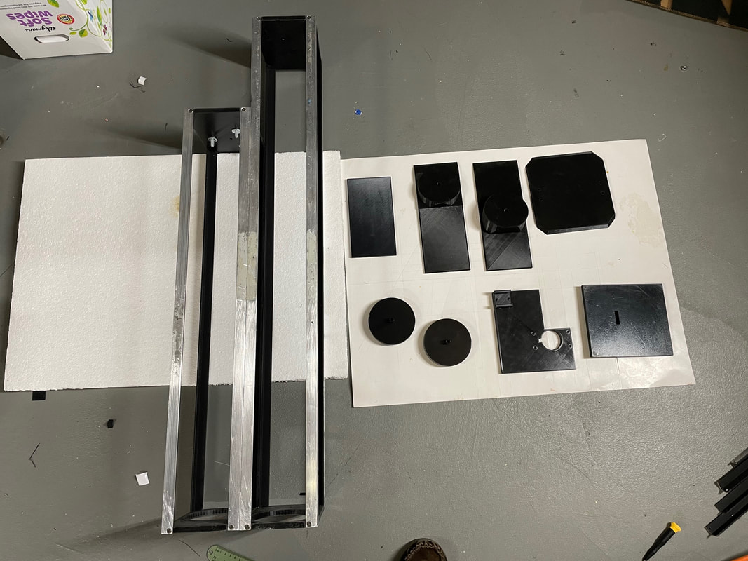
Print out parts#6, 10 (twice), 11, 14, 16, 18, 21, 9 (twice) (not shown in photo below)
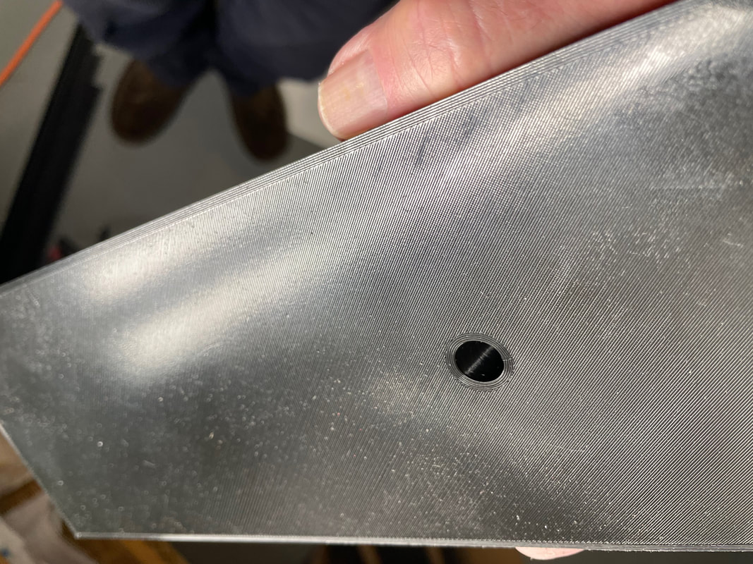
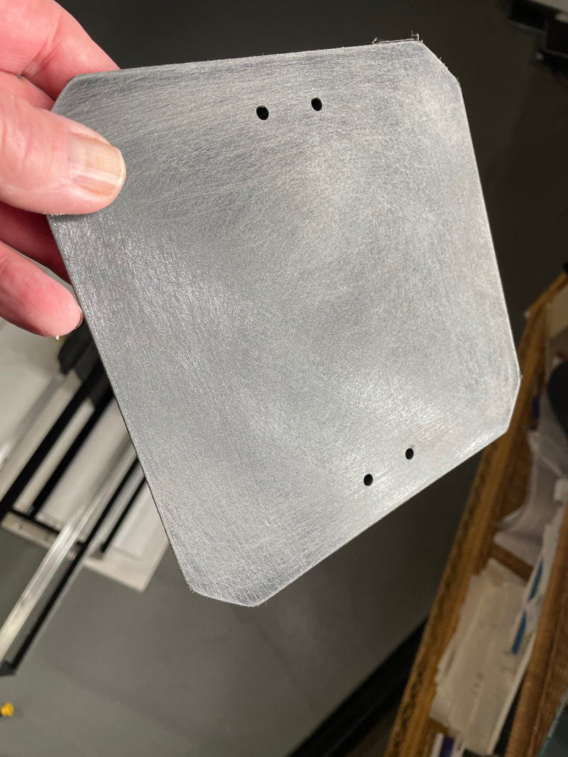
PLA is shiney as printed and you need to rub the inside face of parts 6, 11, 14, 21, to make them matt. As an example here is part#11 before rubbing with 100 grit sand paper:
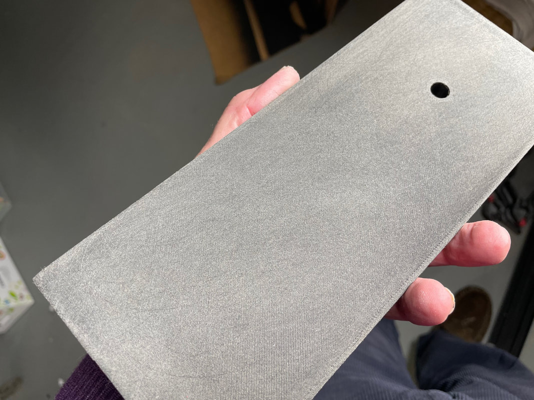
Here is the same inside face after being rubbed with sand paper for a couple of minutes:
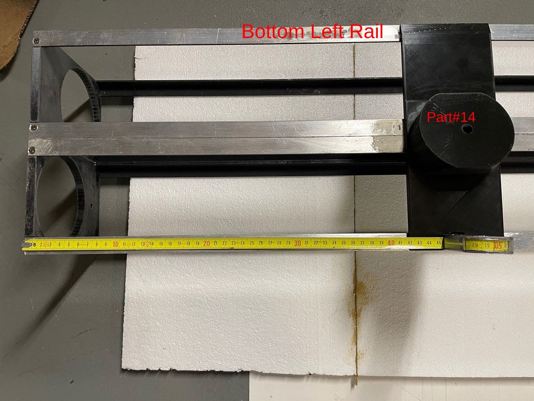
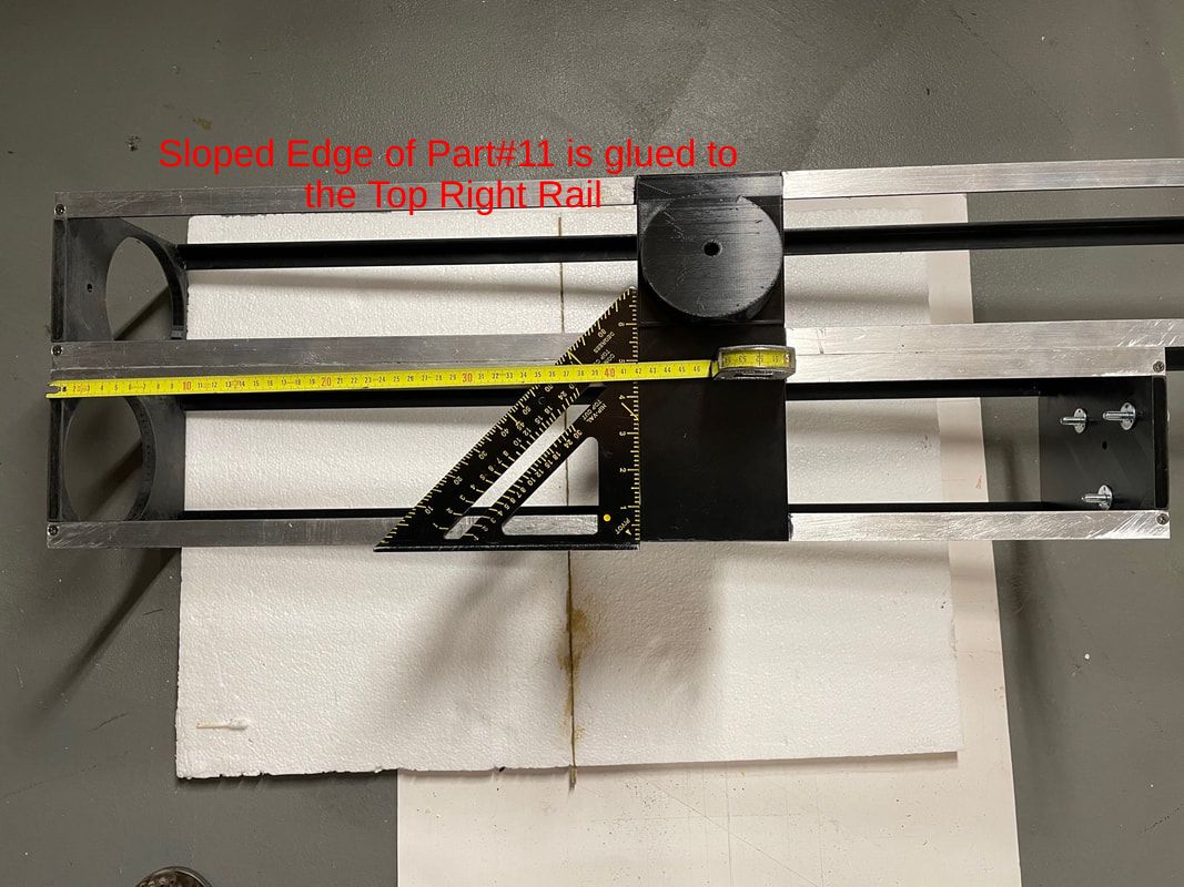
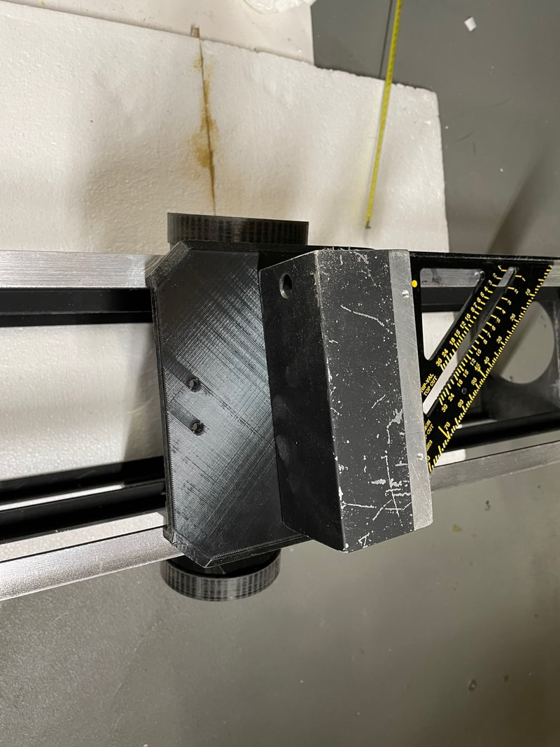
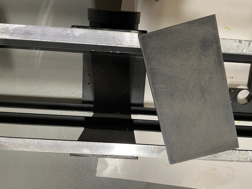
Lay the frame down with the front on your left. You are going to glue part#14, 420mm from the front of the frame, see picture. Make sure you pick up part#14, it has the altitude bearing at its middle, and make sure that you orientate such that the sloped end is going to be positioned on the bottom left rail. Make a mark on each side of part#14 so you can place it back in the same place after applying the glue.
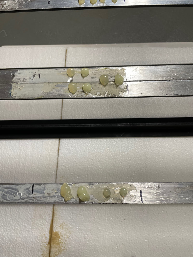
Apply the glue between the marks. Shown in the photo below is the two part plastic welder before its mixed and spread between the marks.
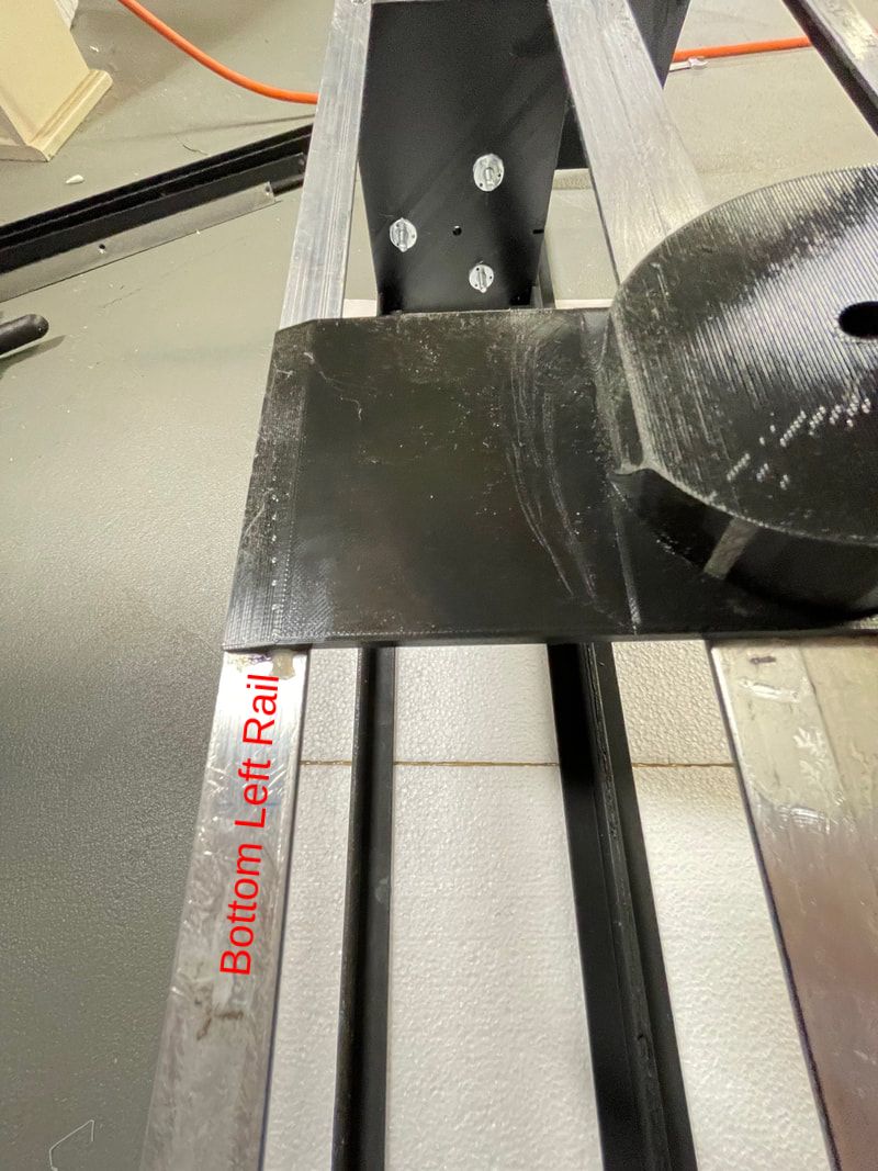
Place part#14 on to the glue and make sure it is in the correct orientation. The chamfered (sloped) edge is on the bottom of the frame. This is VERY IMPORTANT, if you place part#14 upside down or misaligned and the glue sets up you will have to destroy the part to detach it from the frame and you risk bending the aluminum. Think twice before you push the part on to the glue.
After about 15 minutes the plastic welder will have set up and you can turn the frame over as shown below:
Now measure 420mm from the front of the binoscope and position part#11. Make sure it's the correct orientation, this is easier to see than part#14, since the altitude bearing is now at the top of the binoscope rather than the middle. The reason why the two altitude bearings are at different positions on each side of the binoscope is so that the eyepieces tilt towards you by 15 degrees when it will be mounted in the Dobson alt-azm mount, this makes observing the sky more comfortable.
After allowing the glue to set up on part#11you want to glue the bottom edge of part#7 to the top edge of part#8. To do this you will remove part#7 from the frame, apply the plastic welder to the lower edge and then replace part#7, see below a photo of parts#7 & 8 after gluing:
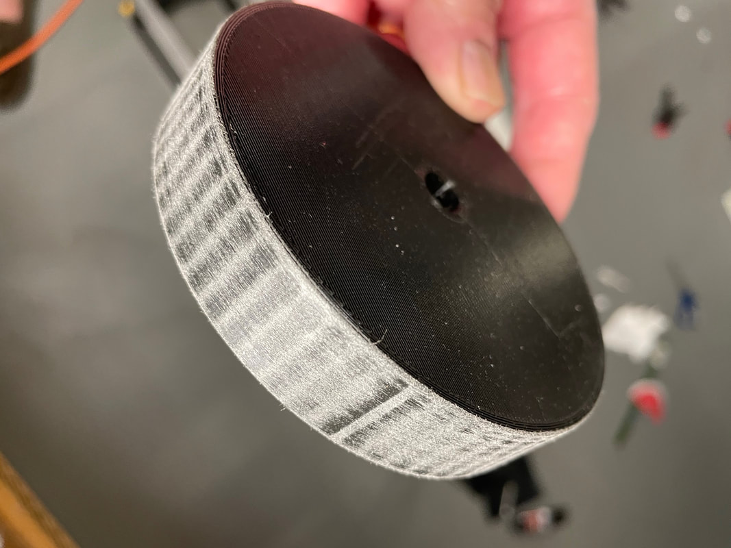
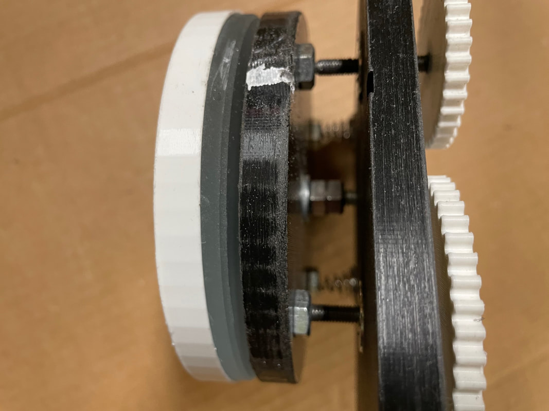
We are now going to prepare the two circular altitude bearings (part#10), Firstly, rub the out edge of each part#10 until most of the 64 flat segments disappear. The surface does not need to be completely smooth, just take most of the edges off:
Now cut two 35mm long lengths of 1/4-20 threaded rod. We are going to glue these through the middle of each part#10:
Next we are going to glue the two circular altitude bearings (parts#10) into the altitude bearing mounts (parts 11 &14):
Spread out the glue on the flat surface and protusion:
Push each part#10 firmly into the two side mounts, making sure that the glued surface of part#10 comes into close contact with the flat mating surface of part#11&14. Your frame should now look like the one shown in the photo below:
Now we are going to prepare and glue the handle stand-off pieces (2X part#9 ) and the handle plate (part#18). Start by rubbing the bottom of part#18 with 100 grit sand paper.
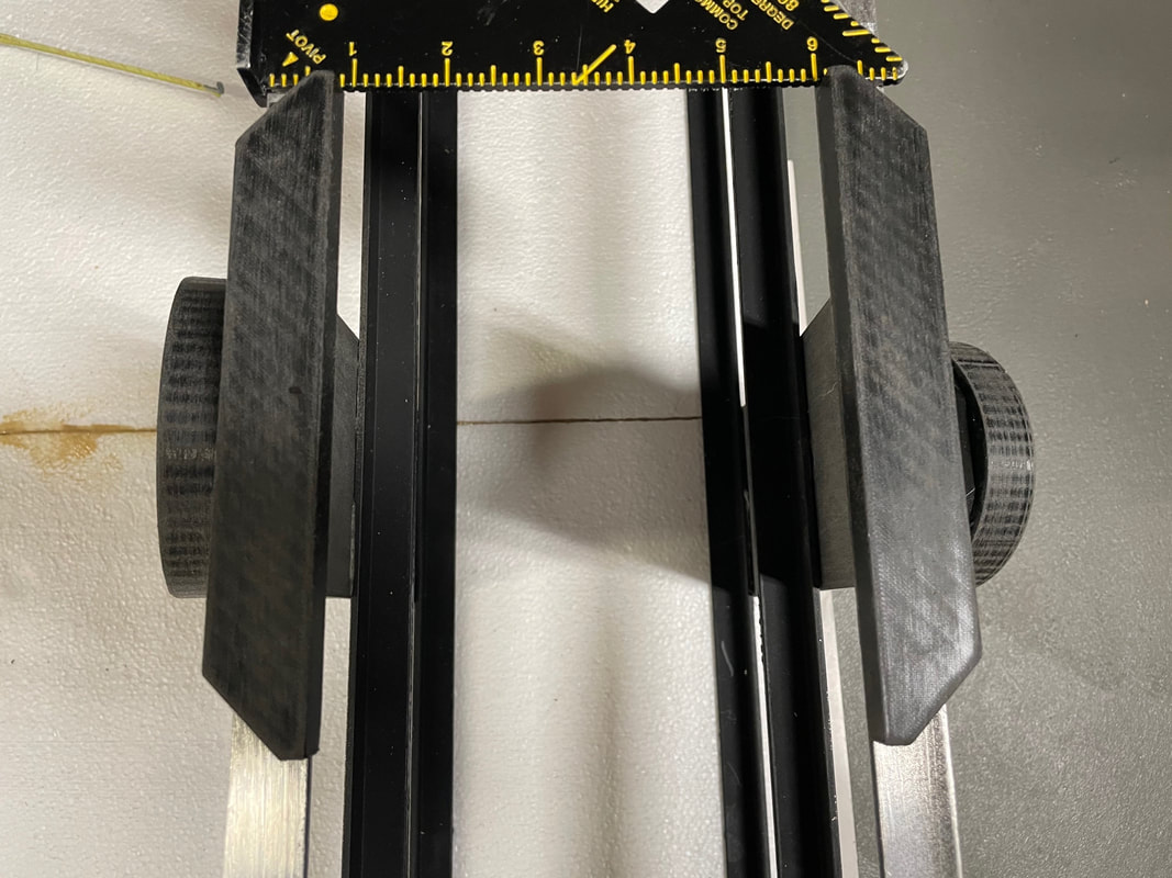
Now glue the two handle standoffs on the top aluminum rails, symmetrically placed above the altitude bearing plates:
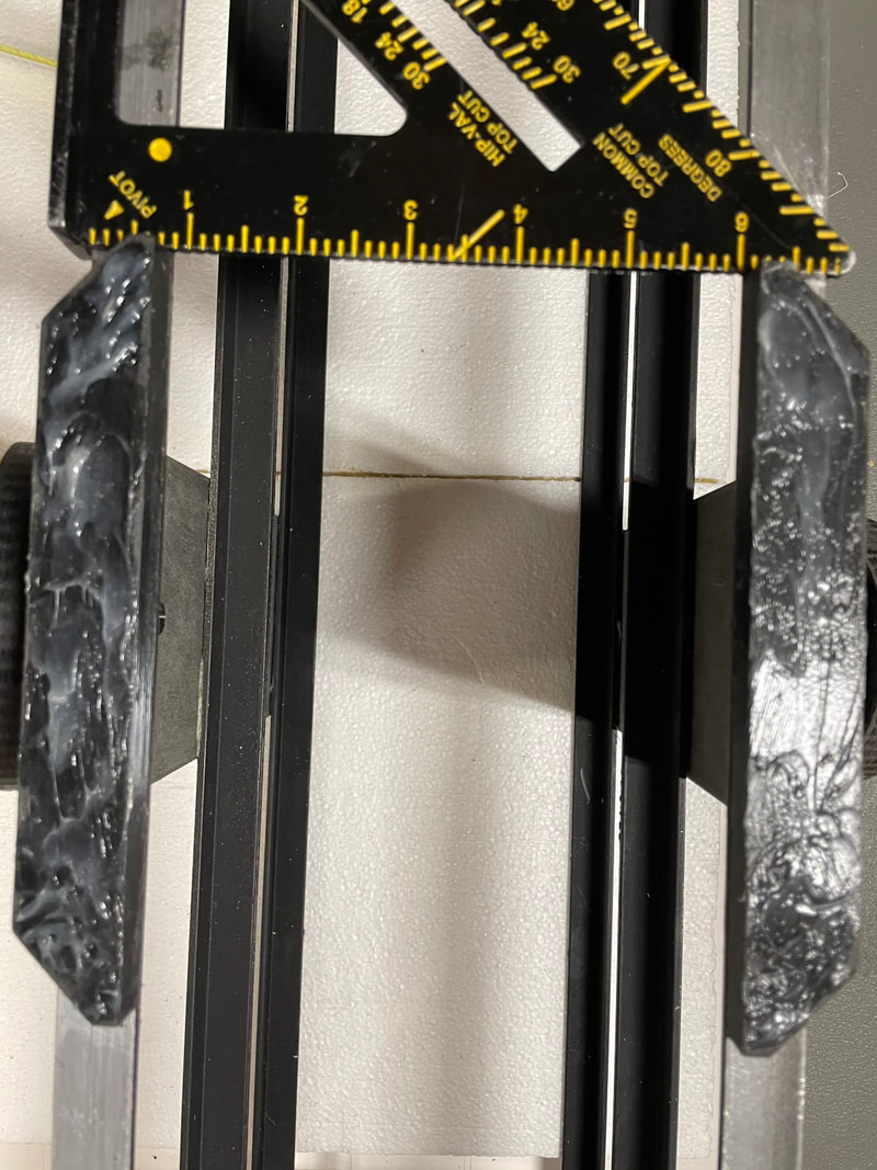
Wait at least one hour to be sure that the plastic welder epoxy has set up between the handle standoffs and the aluminum rails before proceeding to glue the handle plate (part#18). Spread the plastic welder on to the handle standoffs:
Next, position the handle plate on to the glue, making sure that it is orientated so that the handle holes are in line with binoscope, not across it. Place a small weight (but not too much since that might deform the aluminum rails slightly) on the plate to make sure that it does not move while the glue sets up, see below:
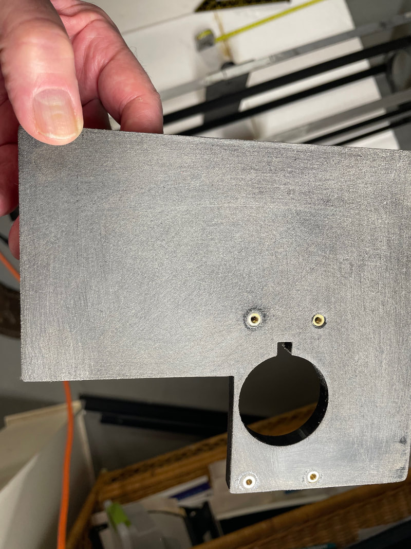
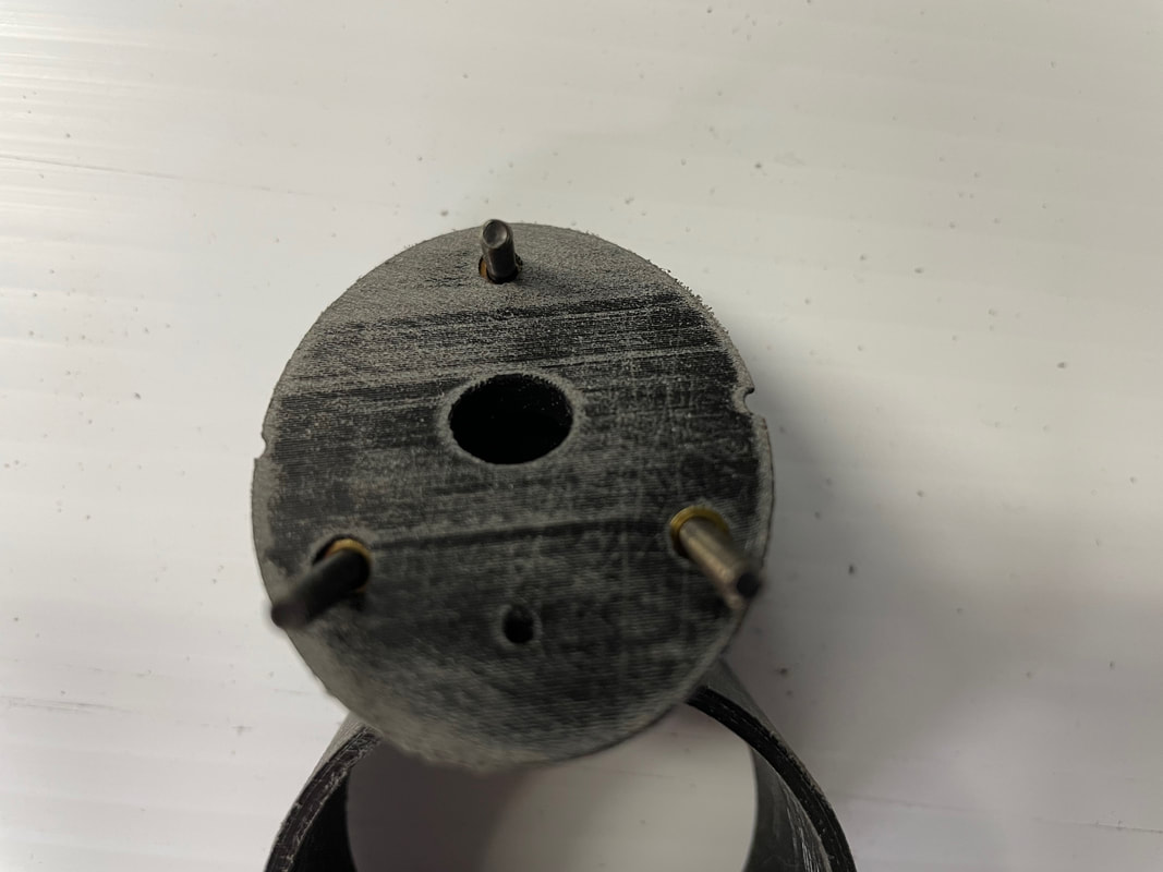
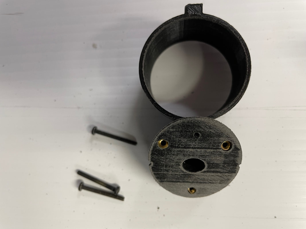
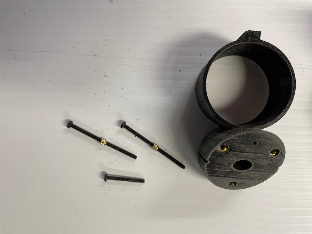
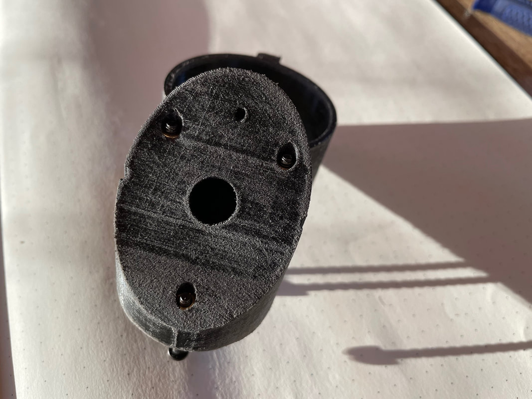
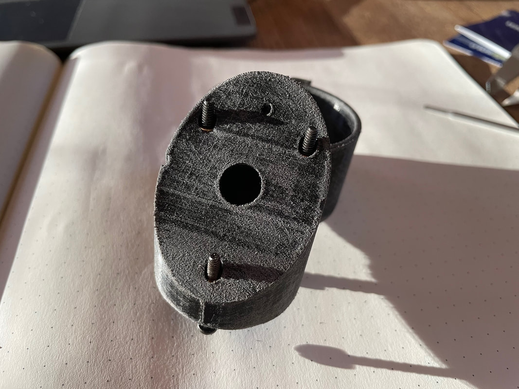
Now we are going to prepare part#6. As you can see its been rubbed with 100 grit sandpaper to take the shine off and 4, 6-32 brass inserts have been pushed or pulled in using a 6-32 bolt from the top side. Use a soldering iron if necessary.
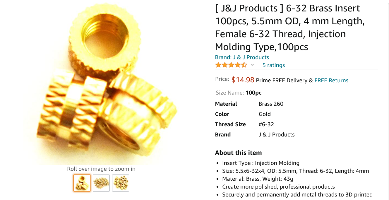
Here is a screen shot of the required 6-32 inserts. You will only need 8 of these but it is difficult to order fewer than 100! If there is any significant interest in building this binoscope I may be able to offer a kit of all the small essential items to avoid each person having to order an unnecessary large quantity of each type of part. Let me know at [email protected]
Using the plastic welder carefully glue part#6 in place on the top front of the aluminum frame making sure it is aligned with the front and sides of the frame. You want to place some glue on the top of part#7 to fully adhere part#6 on 3 of its sides. You can see that I have printed out a "Red Dot Finder mount" and glued it on part #6. This part is available on Tinkercad in my public area.
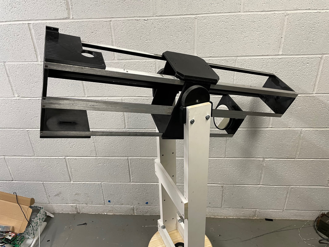
This is the current state of the frame being tested on the Alt-Azm Dobson mount:
Prepare part#16 by taking the shine off the inner surface (the photo shows an older version of part#16. It now has a slightly different mounting slot for the lower secondary mirror mount:
Now apply plastic welder glue to the bottom of the front part of the main frame:
Carefully fit part#16 to the frame making sure it is square and has the correct orientation, where the slot for the lower secondary mirror is directly below the focuser:
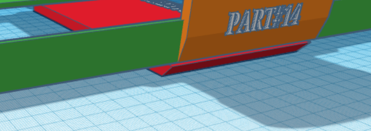
Next we are going to fix the lower panel part#21. First rub the shine off the inner side. The inner side is the longer side where the 45 degree chamfer comes to a sharp edge. You want to glue part#21 where its chamfer meets the chamfer of the right side altitude bearing mount part#14. Tricky to explain but see the screen shot of the 3D drawing below and it should become clear:
Place the frame back on the mount and it should look like this: ( I attached the lower primary mirror to balance the assembly):
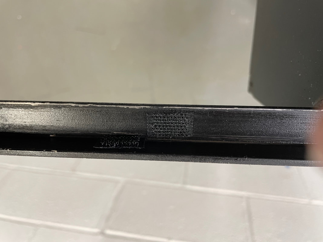
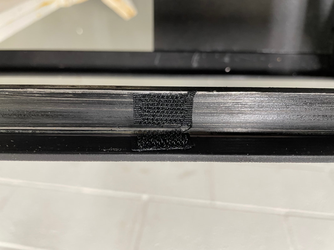
Before moving on to constructing the sliding upper telescope frame there is one last task to do on the upper main frame, and that is to stick on 24 pieces of velcro in 3 locations. Here is a photo of what I mean:
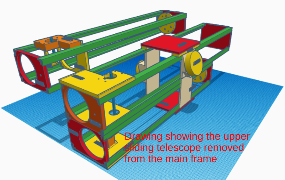
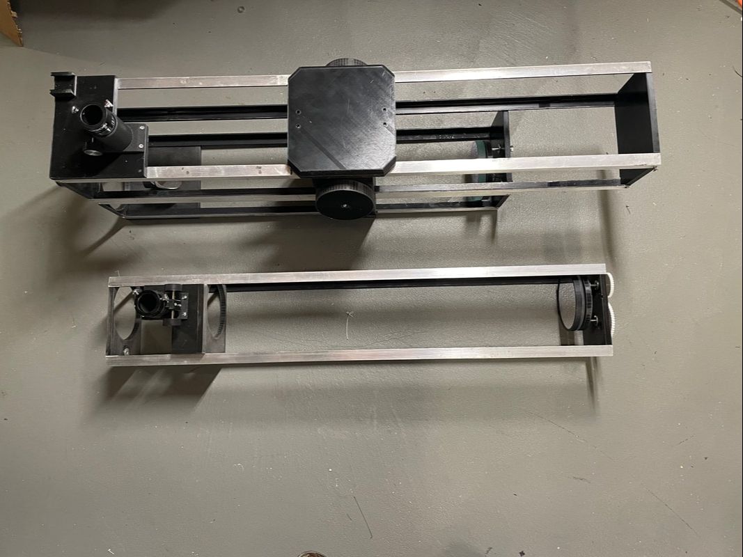
From the photos above you can see that I am talking about the "hook" part of the velcro not the fuzzy part. What we are creating are flexible guides for the upper sliding telescope frame inside the upper part of the main frame. You want to put one set of velcro pads about 6 inches from the front of the main frame, another set in the middle of the frame and a third set about 6 inches from the rear of the main frame. Each set consists of 8 small pieces of velcro. You put two pieces of velcro on each inside angle of the aluminum lengths. You are creating velcro guides so that the sliding frame will be supported and centralized in the upper main frame. We have not built it yet but here is a photo of the main frame and the sliding frame side by side. You have to imagine taking the rear plate off the main frame (part#12) and pushing the sliding frame into the main frame (you obviously remove the upper telescope focuser before sliding it in. The sliding frame should be quite tight, certainly not loose, but not too tight either. It should move with a force of a few pounds (~5 to 10). If you zoom in on the photo below you can see some of the velcro pieces on the inner angles at the rear of the main frame. The reason why the upper telescope slides back and forth in the main frame is to adjust the IPD (Inter Pupillary Distance).
You now want to 3D print the following parts to build the upper sliding telescope:
114mm Part#1................(Upper telescope Front plate)
114mm Part#2................(Upper telescope Rear plate)
114mm Part#3................(Upper telescope primary mirror mount)
114mm Part#4................(Upper telescope secondary mirror stalk)
114mm Part#5................(Upper telescope focuser plate)
114mm Part#25..............(Upper telescope structural support)
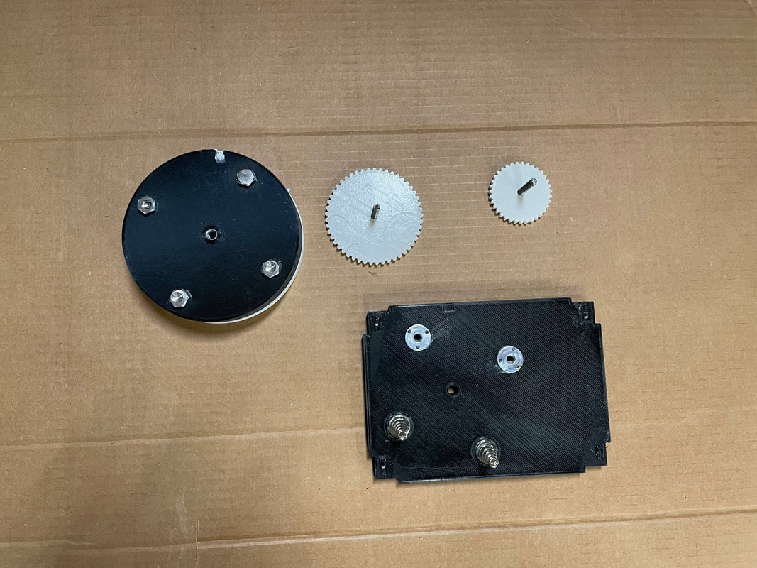
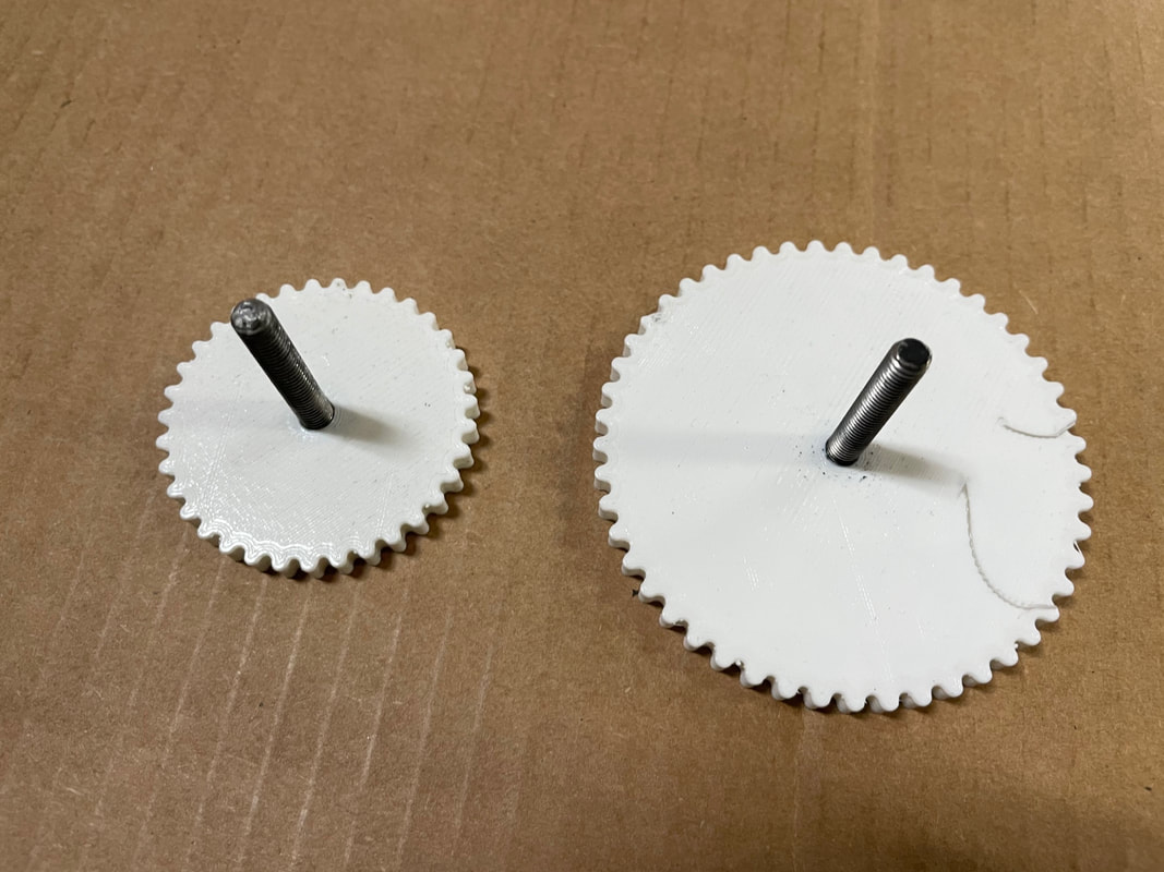
114mm Part#22..............(Upper telescope large adjustment wheel)
114mm Part#23..............(Upper telescope small adjustment wheel)
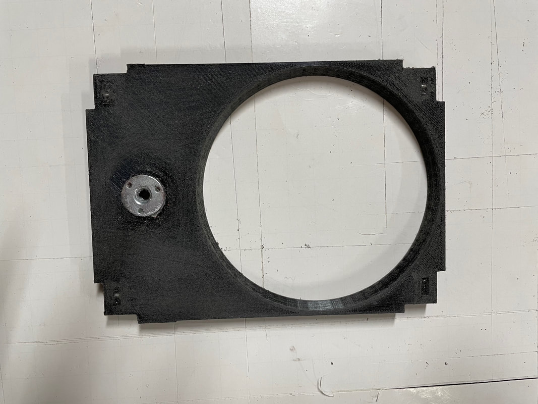
Prepare Part#1, by RTVing 8-32 nuts into the corner slots and gluing (use plastic welder) a 1/4-20 T nut in the hole as shown below. This T nut will accept the 1/4 -20 threaded rod to adjust the IPD:
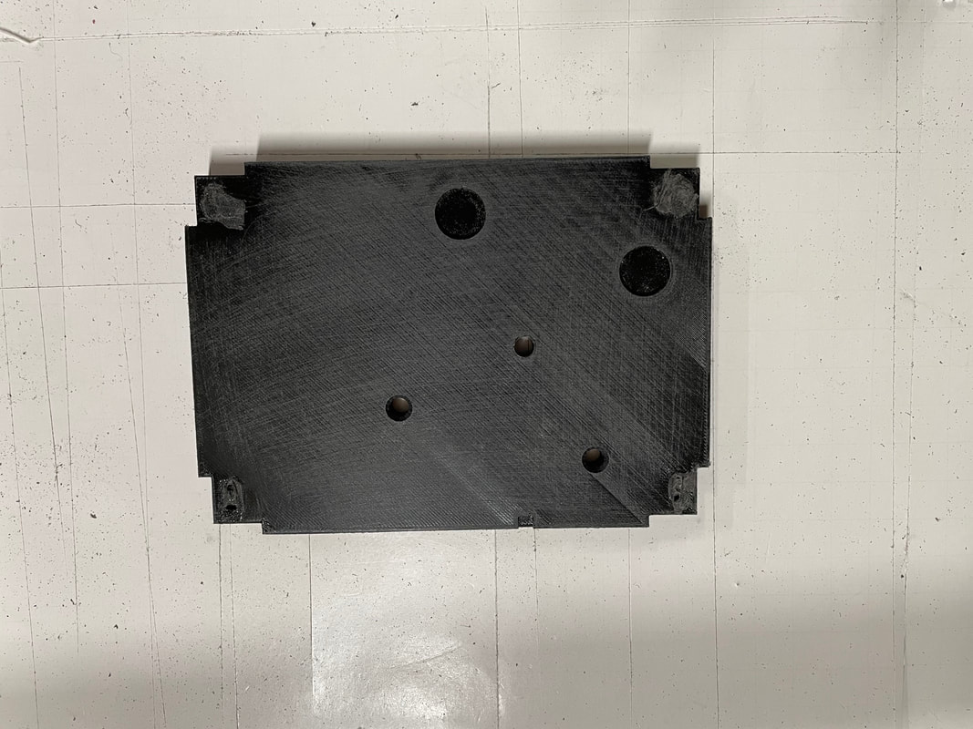
Prepare Part#2. First install the 4 8-32 nuts in the corner slots and RTV in place:
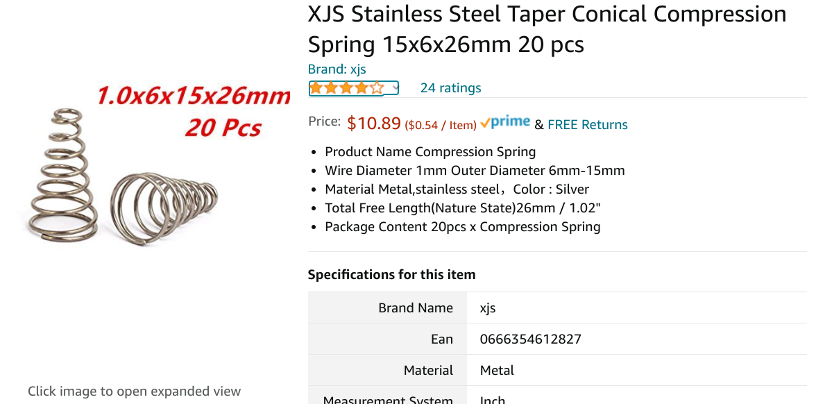
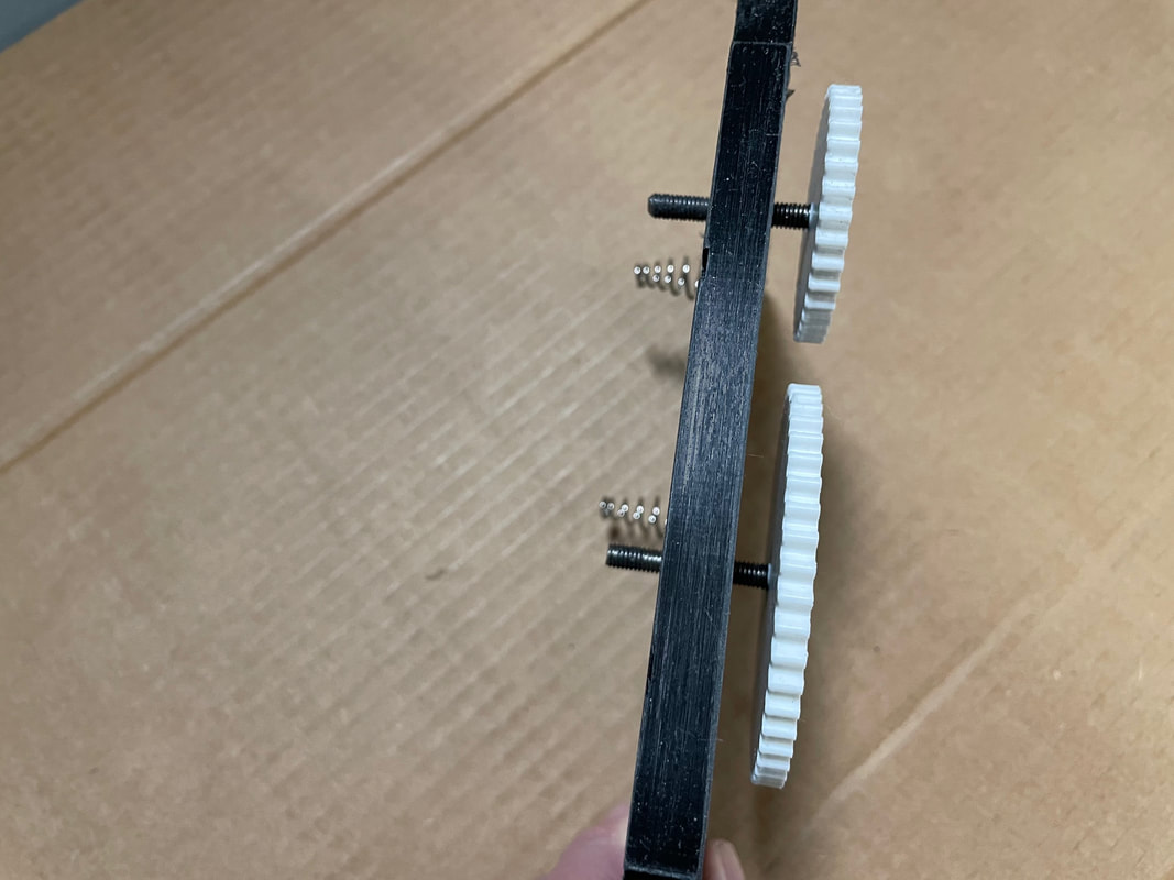
You need to buy two taper springs as shown below. Unfortunately you will need to buy 20 of them and that is why if there is sufficient interest I will prepare kits for all the different parts and supply just the correct amount of springs, screws, nuts, cut and drilled, aluminum angle, etc. Contact me at [email protected]
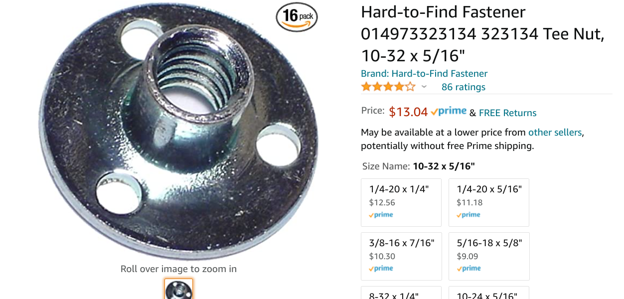
These are the 10-32 T nuts that are used for the image alignment bolts:
Glue the 10-32 T nuts and the springs using the two part plastic welder
Prepare the structural support part#25 by gluing in the 4 corner 8-32 nuts and rubbing the shine off the surface of the PLA and/or paint it flat black.
Bolt part#25 into the frame with the extended edge at the top with the aperture in line with front face plate aperture, see photo below:
We are now going to set up the secondary mirrors and align them. This is going to take some explaining so please be patient.......let me know if you are reading this and thinking about making one of these astronomical binoscopes....thanks.
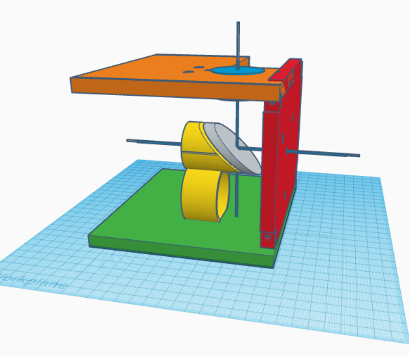
Ok, so let's start looking at how to position the upper and lower secondary mirrors. To provide the best possible collimation results the secondary mirrors need to be positioned in 3 dimensions within 0.5mm in each dimension. This is never simple but here 3D modeling using Tinkercad becomes extremely useful. Let's look at the lower secondary first:
The above drawing shows part#16 (Lower secondary mounting plate), part#15 (Secondary mount lower telescope), part#13 (Rear plate lower main frame), part#6 (Focuser plate for lower telescope). These parts are all copied and pasted as if you are starting a new Tinkercad design. They are then moved until they are each in their correct position relative to each other but with compressed vertical and horizontal dimensions. A blue crossed line is constructed that defines the center line of the lower telescope focuser and the center line of where the lower primary mirror is mounted on part#13. The only variable here is how far in front of part#15 the 40mm mirror should be glued. The front surface of the lower secondary mirror needs to be 16mm in front of the front surface of part#15. The gap between the front surface of part#15 and the back surface of the mirror is therefore (16-(secondary mirror thickness)*1.41) mm. The thickness of a 40mm secondary mirror depends on the manufacturer and is not fully defined. It varies between 7 to 10 mm. You need to measure the thickness of your specific secondary mirror. Let us assume that it is 8mm ( which becomes effectively 8*1.41=11.3 in the horizontal direction. Then the mirror will need to be stood off by 16-11.3mm from the front surface of part#15, i.e, 4.7mm. This is accomplished by the 3, 4-40 bolts that are held in the body of part#15. It is quite easy to "dial" up 4.7mm since we know that there are 40 turns per inch of movement for a 4-40 bolt. That is 25.4 mm for 40 turns, or 0.635mm per turn. Therefore to move 4.7mm we need to make 4.7/0.635=7.4 turns. To set this up you first turn the three 4-40 bolts until the ends are just flush with the front surface of part#15, see photo. You then turn each bolt 7.5 turns clockwise and you will have set up a plane 4.7mm in front of the front plane of part#15, on to which we are later going to place the 40mm secondary. The extremely fine tuning of the 3, 4-40 bolts will be done when you are actually gluing the secondary to part#15 which is done as one of the very last assembly actions using a collimating laser. This will be explained later.
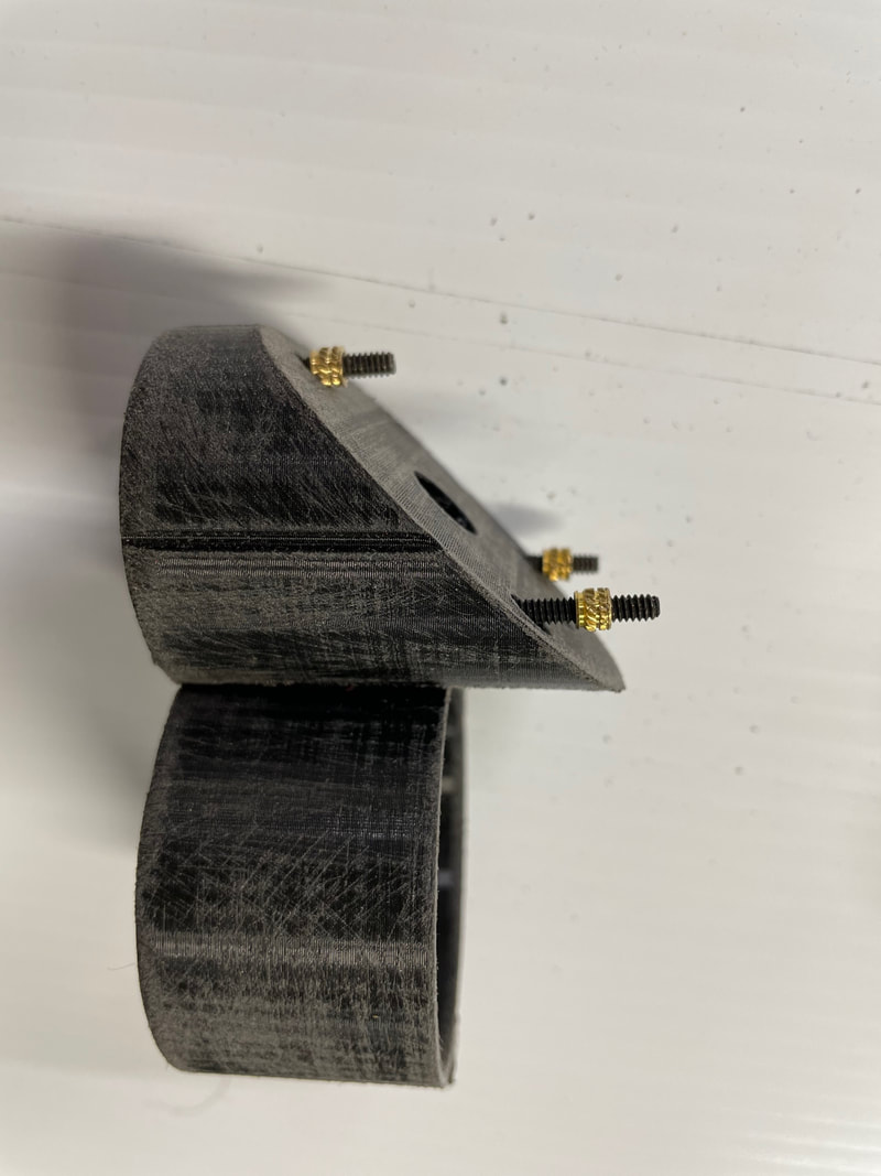
Preparing part#15 prior to gluing it on to part#16:
Shown below are examples of 114mm F8 and 150mm F5 Dual Newtonian Offset Binoscopes
Miscellaneous astronomical odds and ends
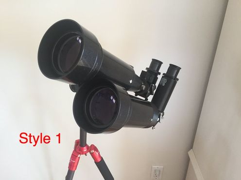
The Celestron 70mm Travel Scope was selected as being the best compromise between, cost, optical performance, reasonably large aperture and weight. For just $60 (when it is on sale on Amazon) it provides good star images thanks to its 400mm F 5.7, fully coated achromat and an apparent field of view of 50 degrees with the included 20mm eyepiece, which provide 20X magnification. The included tripod is quite wobbly and it is difficult to use without significant frustration. Even if you only wanted to start with just one single travel scope I would recommend buying the Neewer Carbon Fiber 66 inch camera tripod with 360 degree ball head (about $95 on Amazon). It is very rigid and weighs about 3 pounds and by using the ball head at 90 degrees it provides a smooth alt azimuth mount. If you want a more compact tripod that fits in the Celestron backpack then purchase the Neewer Carbon Fiber 56 inch Mini Tripod with 360 degree ball head (about $75 on Amazon and weighs less than 2lbs). Both of these tripods can carry the finished binoculars since they weigh less than 5 lbs. and they still fit in the Celestron back pack with the Neewer mini tripod. I found that the mini tripod needed a thin plastic insert in the ball head opening to hold the rotated ball at 90 degrees otherwise in went to about 100 degrees and the binocular mount would hit the side of the tripod. The number of this 3D printed insert in Thingiverse.com is: 3267870
I would not recommend using the 5*24 finder telescope that comes with the Travel Scope, you will be able to point either a single telescope or either style of binoculars much easier if you buy a red dot finder (about $16 on Amazon).
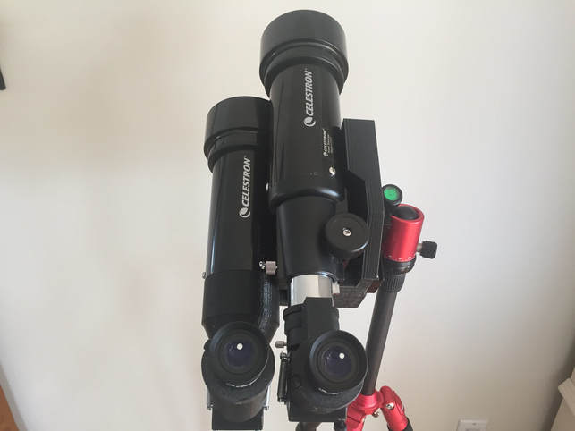
Style1 Binoculars.
This basic design can be found in a book by Norman Butler, title "Building and Using Binoscopes" where it is credited to Dr Alex Tat-Sang Choy in the section "Short Notes on Asymmetrical Binocular Telescopes", page 326.
With the advent of 3D printers is is now much easier for anyone who is interested to combine two refractor telescopes into this binocular configuration.
The project number on Thingiverse which has all the files for the different parts to construct this style of binocular is:
3270039
If you search for petertinkerer on Thingiverse you should see all the parts I've made so far for both binocular styles.
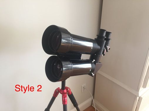
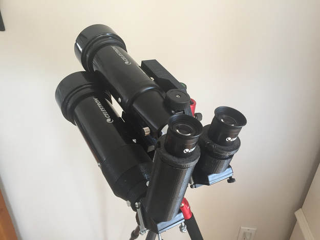
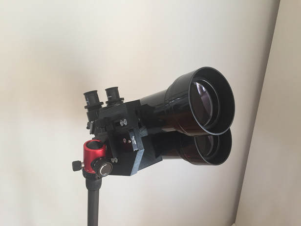
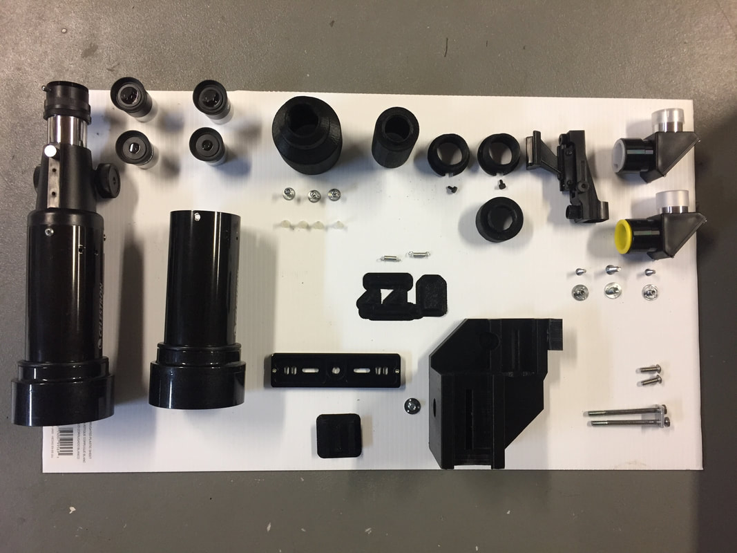
Style 2 binoculars have the advantage of interlocking mechanics (which makes them very robust) and an easily adjustable IPD from 55mm to 75mm. You would need to purchase the two Celestron 70mm travel scopes (~$140), the two 1.25 mirror diagonals from Agena Astro (~$60), the mounting rail (~$13), the red dot finder (~$16) and one of the Neewer tripods (~$75-$95).
| |||
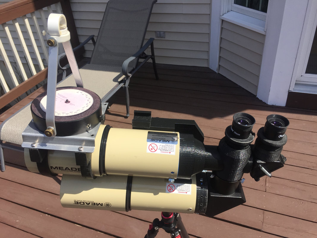
Style 2 Binoculars using two 80mm Meade Adventure scopes. The advantage of this design is that the IPD is easily adjustable, a high tripod is not needed and you do not need an observing chair. The observing comfort is fine up to 75 degrees altitude but observing the zenith does require a bit more gymnastics with the neck, back and knees. These binoculars fit in the original Meade back pack along with the the Neewer mini tripod and fit under the seat on a plane as the personal item, so they can always be carried on the plane and you do not have to risk the "hand luggage" being sent in the hold.
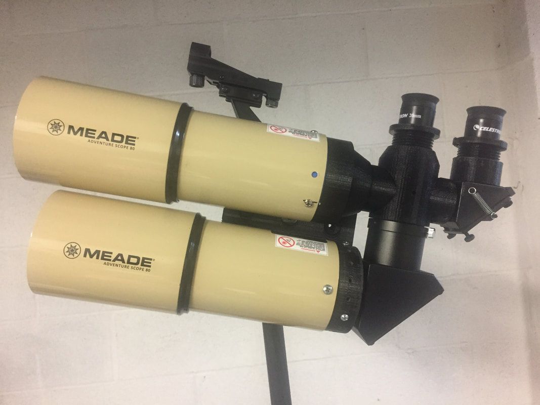
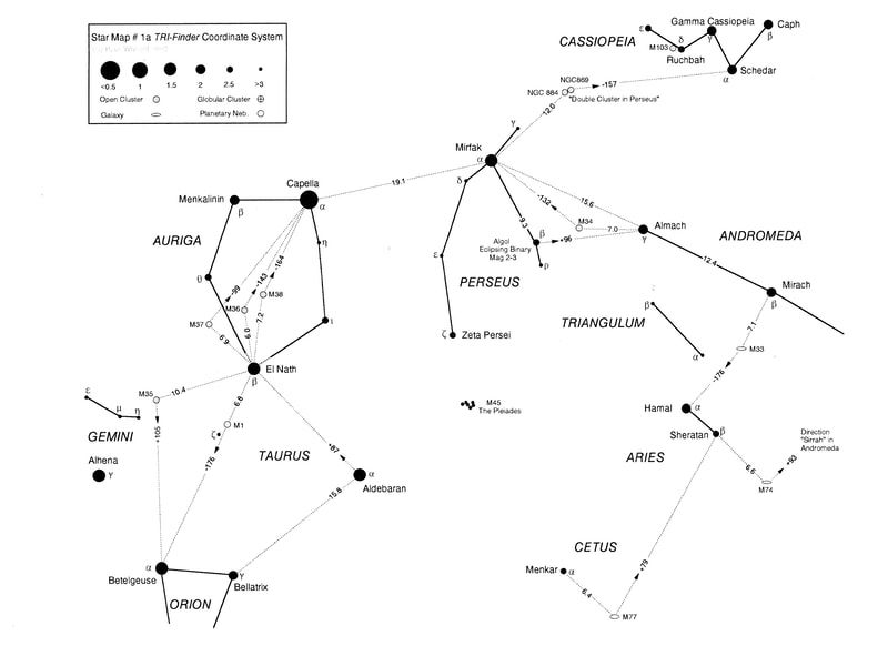
Here are the style 2 binoculars with the DIY triangulation finder attached. I call it the Tri-Finder and it enables the binoculars to be pointed at any celestial object using only the brightest stars in the sky (2nd magnitude or brighter). Essentially the Tri-Finder provides a "heads up display" of an adjustable red triangle in the sky which can be rotated whilst simultaneously moving the binoculars (or telescope) in altitude and azimuth until two points of the triangle fit on the bright stars. You are essentially performing manual "plate solving" which has become all the rage with CCD cameras and sophisticated pattern recognition software. Your brain actually finds this manual pattern recognition quite simple, especially since it only needs ro locate the distance to one bright star and the direction to another Once you have matched the star locations with the specific TRI-Finder projected pattern the binoculars are centered on the the particular Messier object which is sought. I have drawn 11 star maps which show how to locate all the Messier objects using only bright stars. If there is interest in this finder I will provide the 3D files that can be printed to build the Tri-Finder.
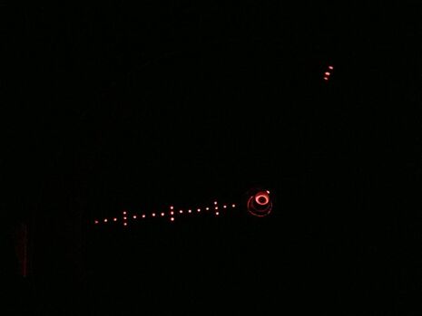
This is the image you see which is superimposed on the sky. The central circle is where the binoculars are actually pointed and represents about a 1.5 degree field of view. The 16 in line dots are separated by 1 degree increments and it is on this scale you place guide star # 1. The 3 vertical dots mark the 5, 10, and 15 degree points on the scale. Guide star #2 is placed on the direction line which in this image is about at 1 o'clock. The direction line can be set anywhere from +70 to -70 degrees and this whole pattern can be rotated by rotating the Tri-Finder disc. By moving the binoculars in altitude and azimuth whilst simultaneously rotating the disc it can be made to "fit" the two guide stars, (it is a lot easier to do this than to explain it). The location of any celestial object can be uniquely defined as an angular distance from a particular star and at a particular angular direction to another guide star. Both eyes are kept open when using the Tri-Finder so it is easy to see the red "triangle" superimposed on the star field. It is like a super red dot finder which enables you to see not only where the binoculars are pointing but to actually point them to within 1 degree of any specific celestial object. The advantage of Tri-Finder coordinates is that they are locked to the stars of the sky thus they are independent of whether you are in the northern or southern hemisphere, you do not need to know your location or the local time and the mount does not need any particular alignment to the horizontal or vertical. You just open the tripod and start locating the desired celestial object. To demonstrate the format of the Tri-Finder coordinates consider M37 in Auriga, they would be:
M37, El Nath (6.9), Capella (-99),
which means M37 is located 6.9 degrees from El Nath with an anti-clockwise rotation angle of 99 degrees. The negative sign in the direction angle means an anticlockwise rotation angle where as a positive direction angle means a clockwise rotation angle. To use the Tri-Finder to locate all the NGC objects you do have to learn where the basic constellations are and be able to identify about 40 of the brightest stars in the sky but that is what makes it a great learning tool which so often the modern GOTO scopes fail to do. However, to get started you just need to locate a few bright stars in the current evening sky and by using the appropriate star map you can start locating at least the main Messier objects within a few minutes. (A full description of the TRI-Finder together with the high resolution star maps is given in the PDF file below).
Please contact me if interested at : [email protected]
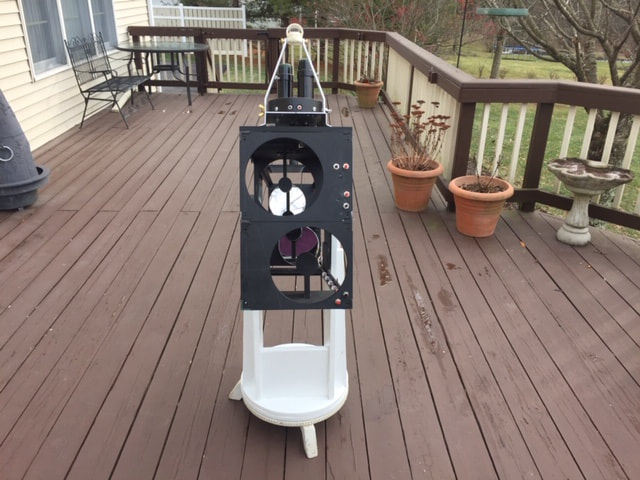
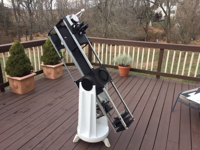
Here are some pictures of my 6 inch F8 Dual Newtonian Offset Binoscope I have just completed. Nearly all the mechanical parts are 3D printed.
I have always been so pleased with the views of my old trusty 6" F8 scope made over 30 years ago that I decided to make this Dual Newtonian, Offset stacked, Binoscope. The 46mm of lateral offset between the individual scope axes provides for a very comfortable viewing position with the angled eyepieces. The angle the eyepieces make with the binoscope axis changes from about 55 degrees with an IPD of 55mm to 40 degrees when the IPD is opened up to 75mm. These angles all result in a comfortable viewing position from horizon to zenith. As can be seen in the 1st photo there are conveniently located push buttons for the motorized X-Y convergence of the images and the lower buttons are for changing the motorized IPD from 55mm to 75mm. What has made this a practical design is the advent of inexpensive 3D printers. There are 20 individual 3D printed parts used in the construction of the binoscope and 12 lengths of aluminum angle. The cost breakdown is as follows:
2X6" F8 mirrors $260
1X 31mm secondary mirror $40
1X 50mm secondary mirror $50
2X Focusers $70
12 lengths of 3/4 inch aluminum angle $75
20 3D printed parts (Cost of the PETG plastic)
$50 (you need to have a $400 3D Printer)
Corrugated plastic Light Covers $25
2 Motors for X-Y image adjustment $40
Miscellaneous screws and glue etc $100
Eyepiece cost not included, but two inexpensive plossls work well with the long focal length.
Useful magnification range from 38X with 32mm Plossls to 305X with 10mm Plossls and 2.5X Barlows.
I will be providing the .STL files of all the 3D printed parts on Tinkercad
The weight of the binoscope is 25 pounds with eyepieces and the classic Dobsonian mount weighs 20 pounds so they balance each other and can easily be carried together.
