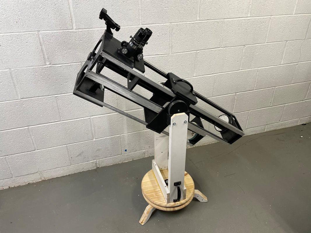
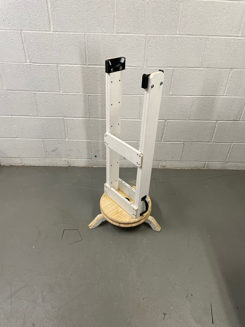
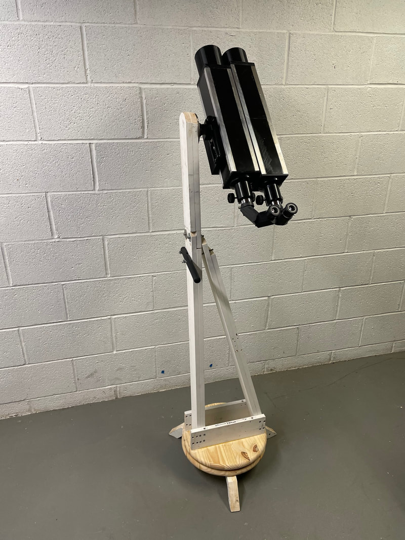
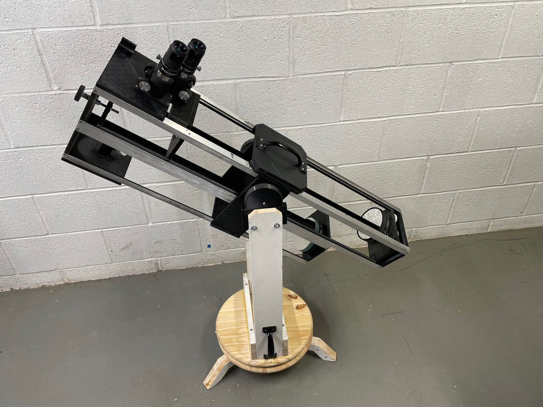
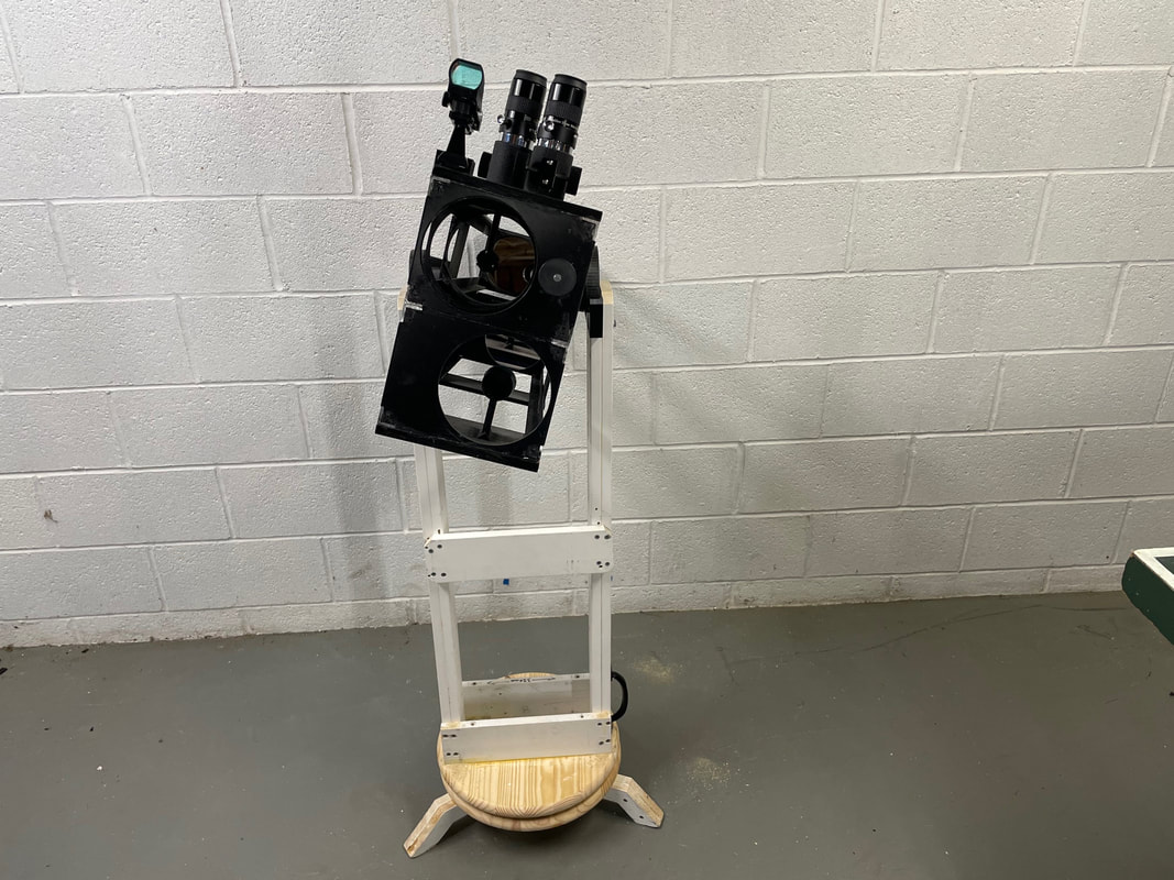
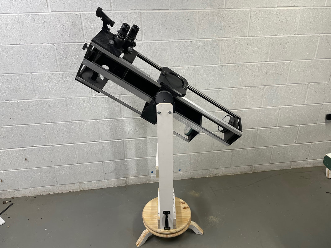
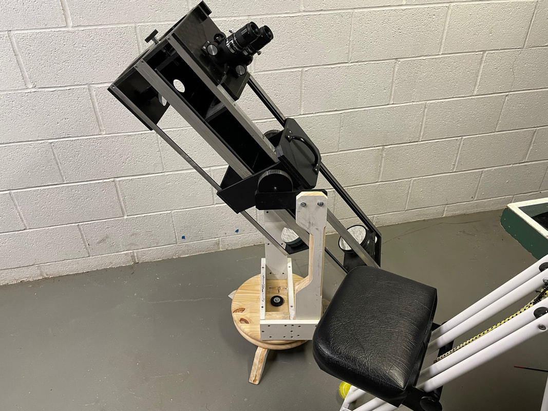
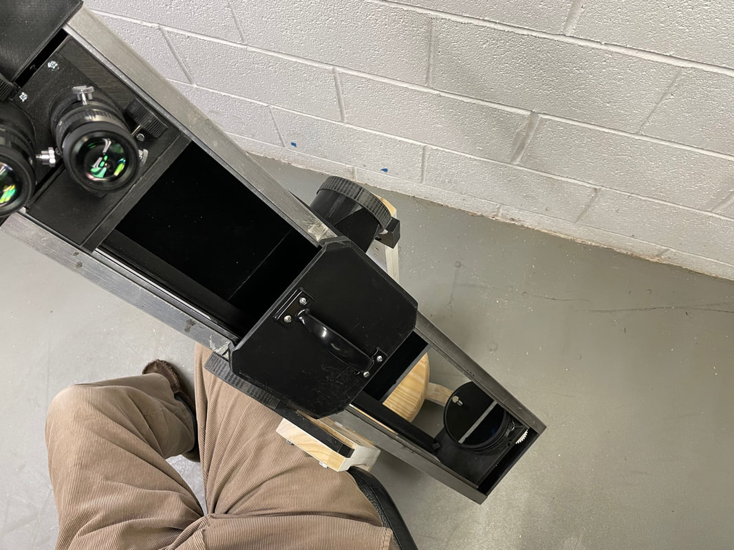
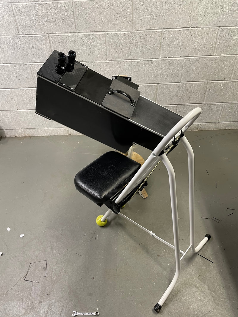
Here are some of the possible configurations of this Alt-Azm mouint:
Short, dual altitude bearing arms, for the 114mm Binoscope for 5th graders
Longer dual altitude bearing arms for comfortable observing with the 114mm Binoscope for adults:
Short single arm with 1 inch pipe fitting for the altitude bearing for the 150mm F5 Binoscope:
Long altitude bearing arms plus an extension for observing with the 80mm F7.5 Binoscope. This set up is used with an adjustable height observing chair. If you think you will be using the mount in this configuration frequently you want to glue and screw the legs 3 inches further out to provide more stability.
There are endless variations for building Dobsonian style, Alt-Azimuth mounts. They can be true works of art, built by wood working craftsmen or just functional designs which get the job done. The design here is of the latter category and is given to help new comers to Amateur Telescope Making. The design is simple and functional and uses easy to find parts. Here are the parts you need to purchase
1) 3 lengths of 1"X4"X 8 feet primed pine board. I bought them from Lowes at around $10 each
1) 3 lengths of 1"X4"X 8 feet primed pine board. I bought them from Lowes at around $10 each
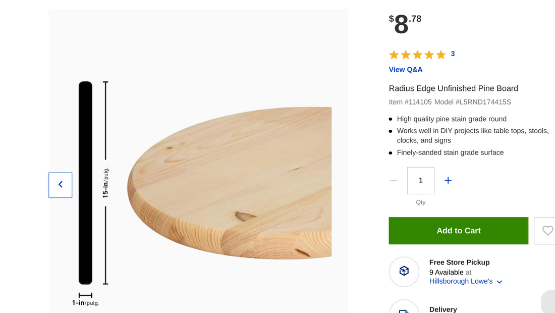
2 ) Two 15 inch diameter by 1 inch thick pine wood discs, available also from Lowes. They cost about $9 each
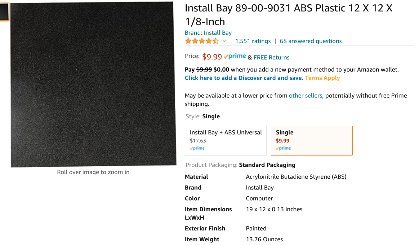
3) One piece of 12"X12"X1/8" ABS plastic sheet which cost about $10 from Amazon. It will be used as the friction surface for the movable azimuth bearing.
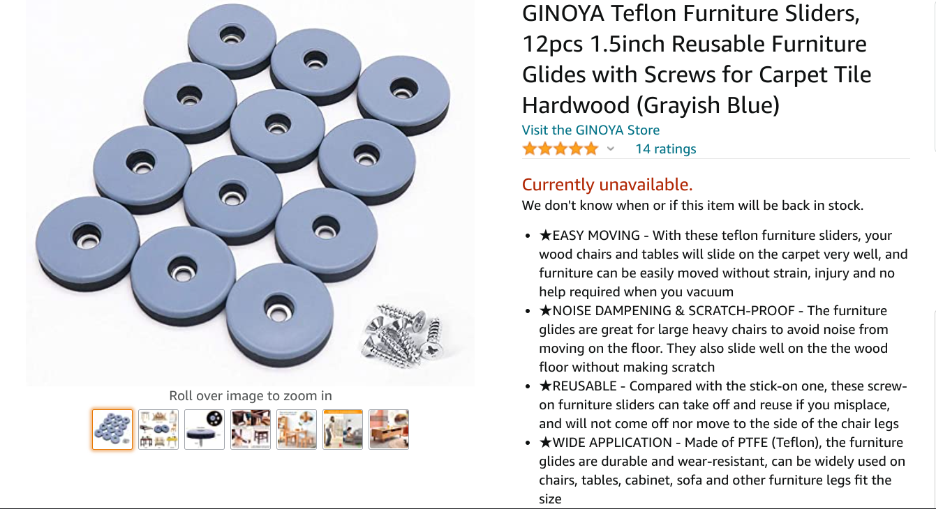
4) One packet of teflon furniture sliders, approximate cost $12. I just made the screen shot below and I see that they are currently unavailable. I hope they will become available again soon since this particular slider provides just the correct amount of friction and stiction when sliding against the rough side of the ABS plastic sheet.They are attached to the lower wooden disc which acts as the fixed part of the azimuth bearing. If you are unable to find these teflon sliders you will have to buy a small sheet of white teflon, about 1/8" thick, and cut out 3, 1.5 inch discs. The key to a smooth, non jerky, azimuthal bearing is to have the stiction coefficient only very slightly higher than the friction coefficient between the two materials.
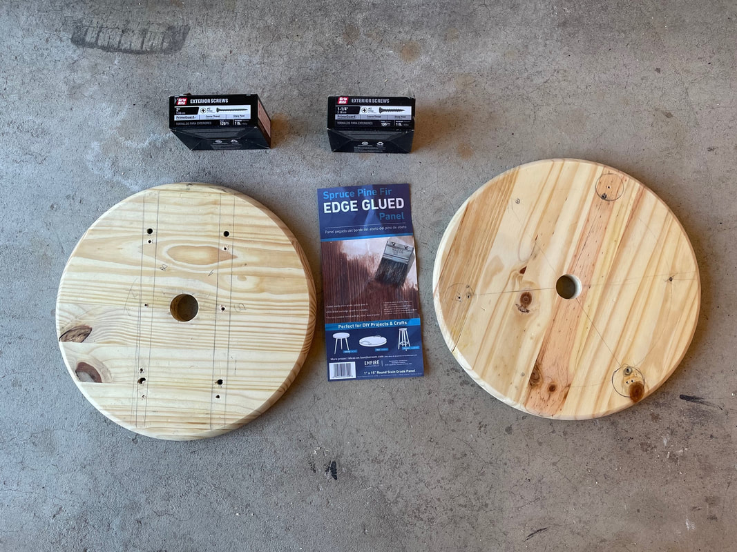
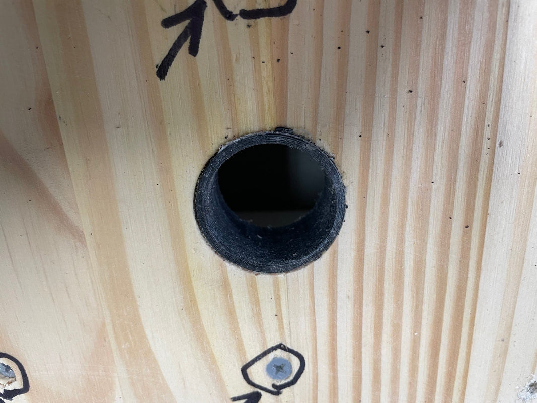
5) One packet of 2 inch screws and one packet of 1 1/4" screws, see photo below I took this photo after I had drilled the center holes into the wood discs. Before proceeding any further with the build I would suggest that you drill the two holes now and waterproof the soft pine by spraying them with polyurethane. Drill a 1 1/4 inch hole in one disc and a 1 1/2 inch hole in the other. The one with the small hole will become the lower, fixed surface, of the azimuth bearing and the other will become the movable part of the azimuth bearing.
6) Print the following 3D parts under the file names:
-114mm Part#30 Binoscope Mount
-114mm Part#31 Binoscope Mount
-114mm Part#32 Binoscope Mount
-114mm Part#33 Binoscope Mount
-114mm Part#24 Binoscope Mount (Print 3X)
These designs can be found on Tinkercad in my public area; search for "Petertinkerer" under people or directly for the file names under 3D designs.
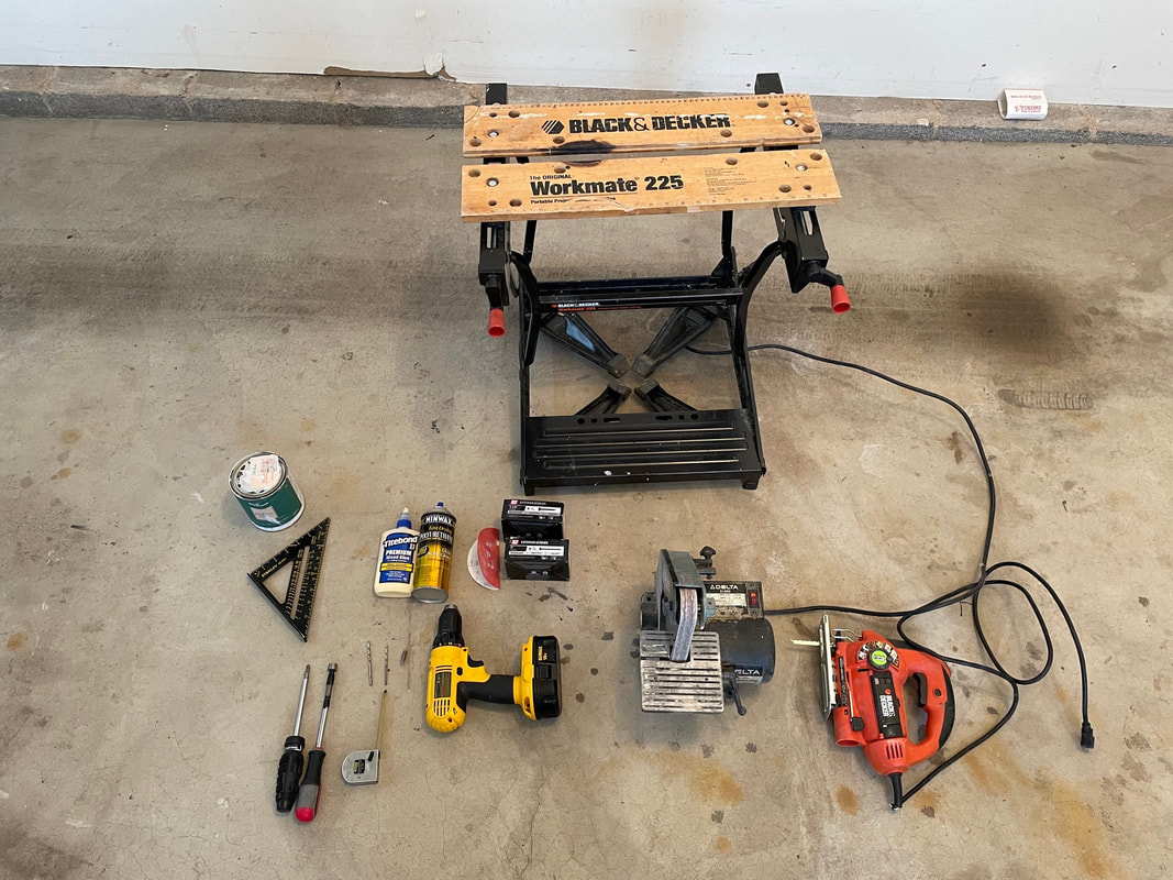
7) Tools required:
This may not be every tool used, but the photo shows the basic set that you will need to make this Dobson style, Alt-AZM mount,
This may not be every tool used, but the photo shows the basic set that you will need to make this Dobson style, Alt-AZM mount,
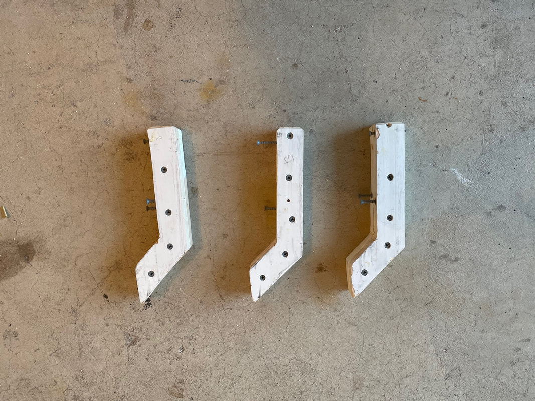
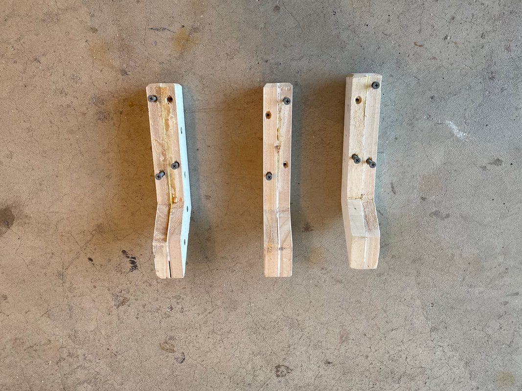
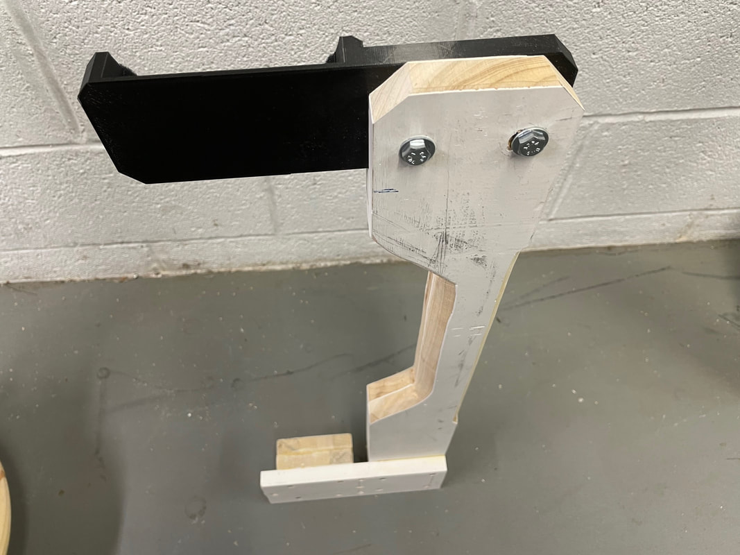
Let's start by making the 3 legs. First cut 6 pieces of the 1X4 pine 240mm in length (make them 300mm long if you will using the mount with the 80mm refractor binoscope for greater stability). Please excuse the mixing of inches and millimeters. It's just easier to use millimeters for lengths but wood sizes are in defined in inches, but not really since the "1X4" pine is actually 3/4 inch by 3 1/2 inch. All the 3D parts are defined in millimeters when using Tinkercad. Cut the 6 pieces into the shape shown below. Start by reducing the width of the wood pieces to 70 mm from 87mm. Make a cut down the middle of the wood pieces (35mm from edge) for 150mm then angle down by 45 degrees to finish the cut out. Complete the piece by cutting off the end at 175mm, angled down at 45 degrees. You now glue and screw two of these pieces together using wood glue and 4, 1 1/4 inch screws. Clean up and square off the edges using the 1 inch belt sander.
After the glue has fully set up, drill 4 vertical holes with a 3/16" drill through each leg, making sure to avoid the horizontal screws holding the two pieces of each leg together.
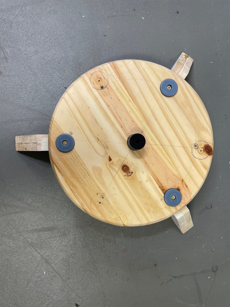
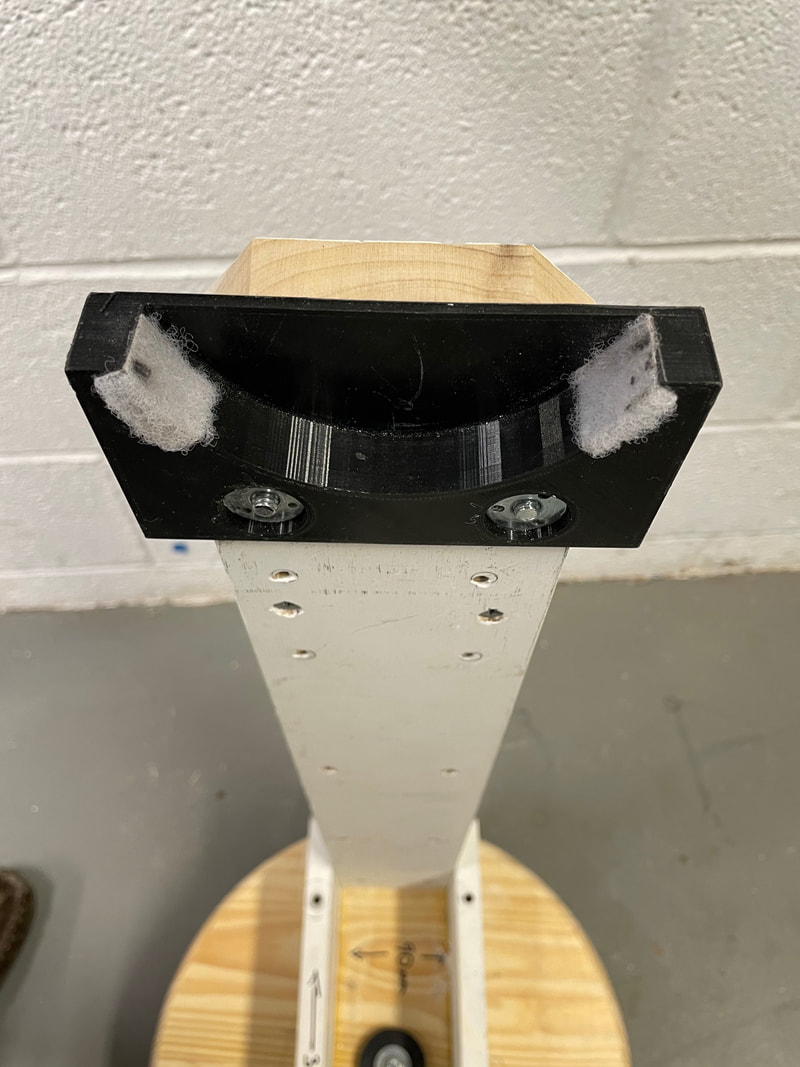
Next glue and screw the 3 legs at 120 degree separation on the lower surface of the fixed wooden disc (the one in which you have drilled a 1 1/4 inch hole through its center), The photo below shows this and also shows the 3D printed part#30 glued into the 1 1/4 inch hole using Devcon Plastic Welder. As a final step on this part, glue a 1/4-20 T nut into the bottom of part#30, as shown in the photo.
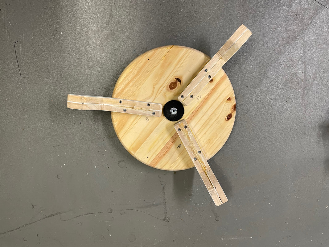
Tun the part over and screw in the 3 teflon sliders in the location as shown below.
Next glue the 3D printed part#31 into the 1 1/2 inch central hole of the upper wooden disc. This is the movable azimuthal bearing of the alt-azm mount. Glue part#31 into the hole using Devcon Plastic Welder.
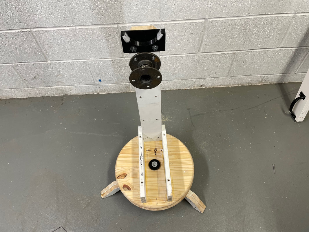
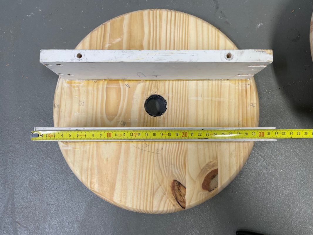
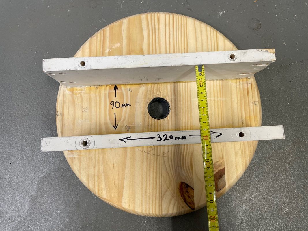
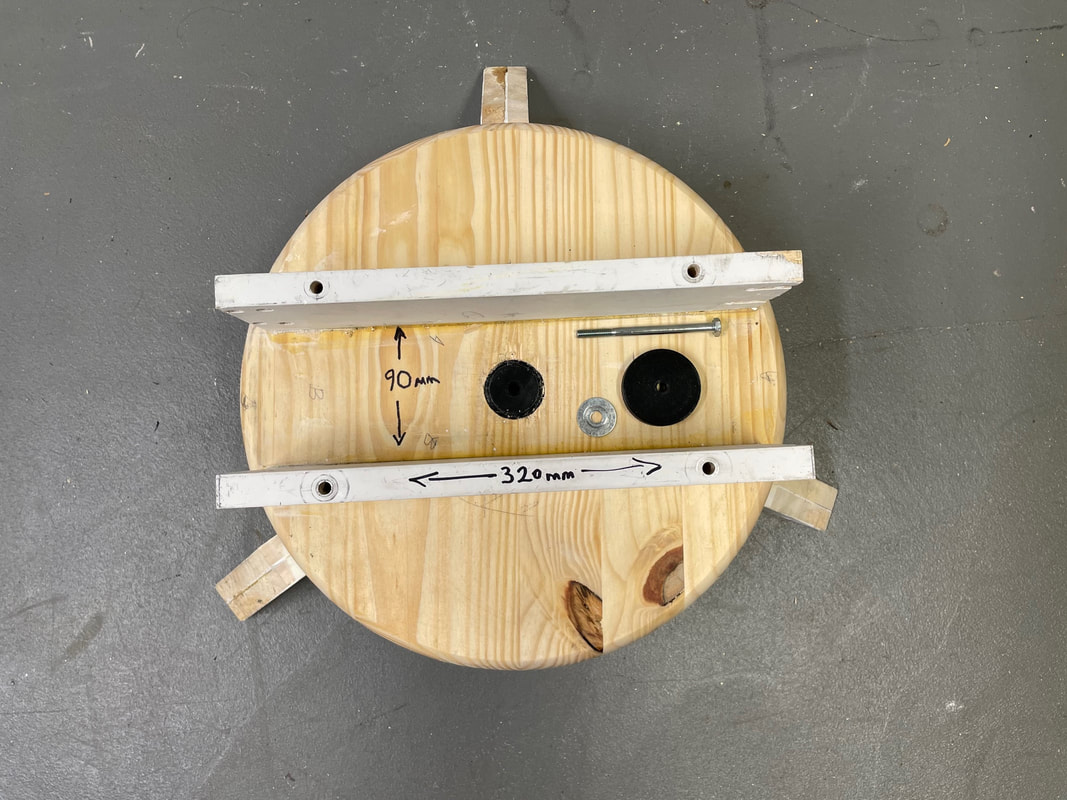
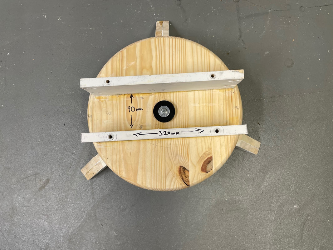
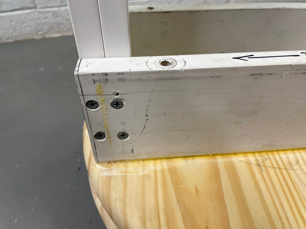
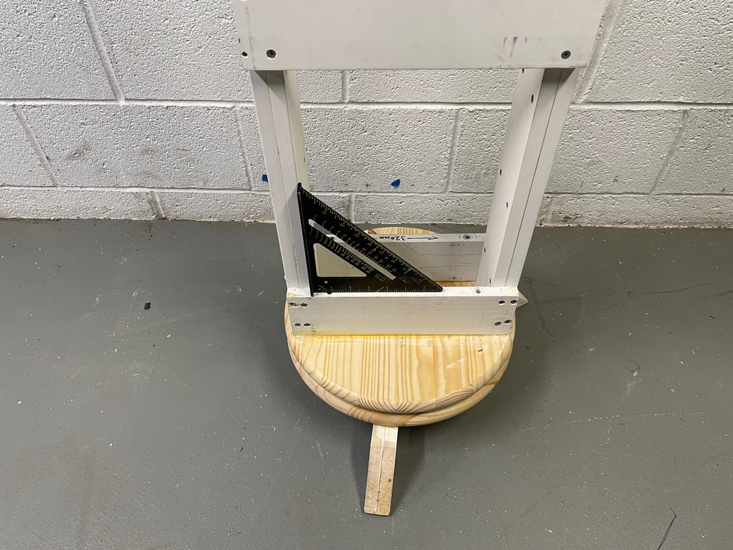
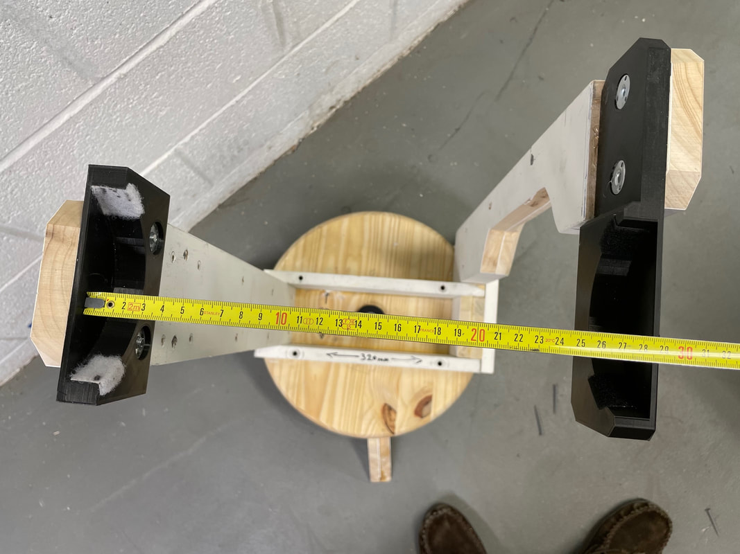
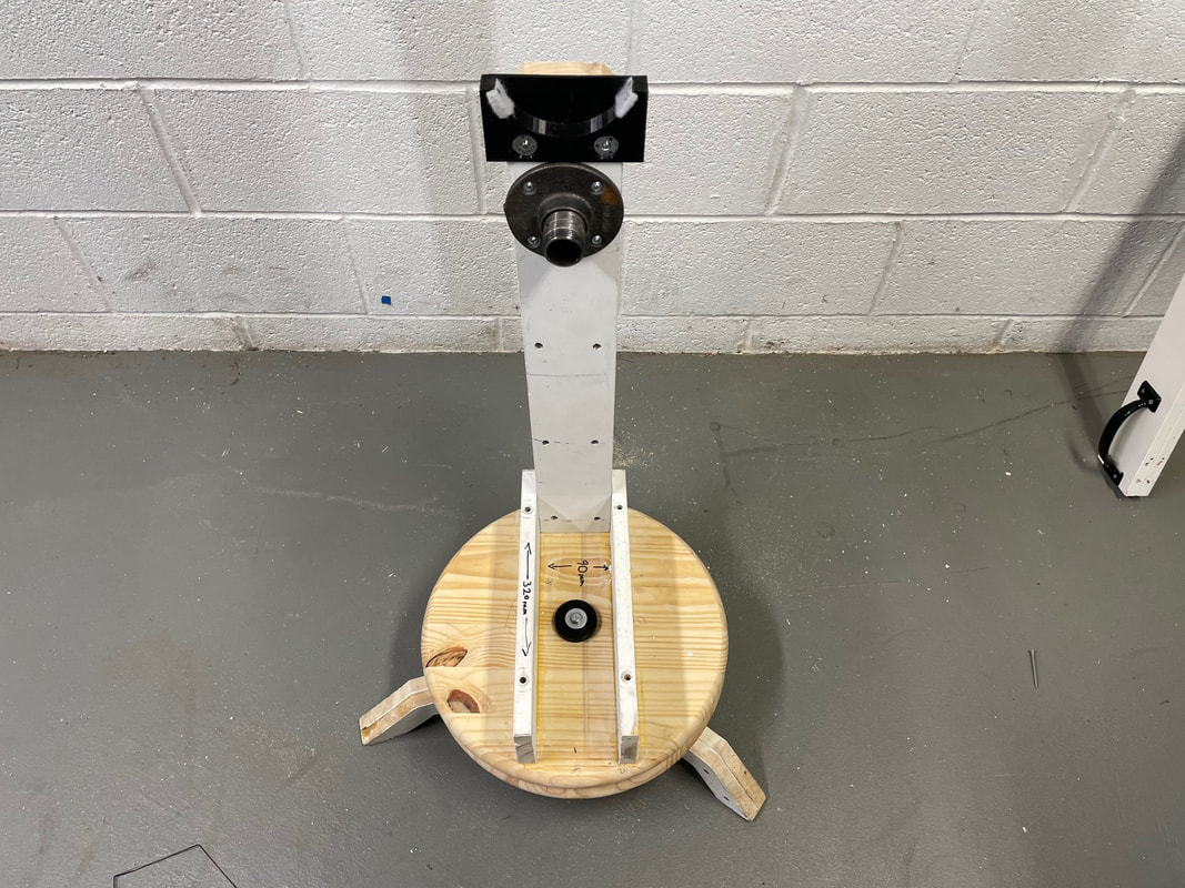
Next cut two lengths 320mm long. You are going to glue and screw these pieces as shown below. Ignore the 4 holes that are visible in the photo. These holes were drilled when I was going to use 1/4-20 bolts to fix the pieces to the base. The two pieces are now glued and screwed from the bottom, see second photo here:
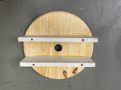
The rwo 320mm long pieces are screwed in from the bottom of the wood disc after applying glue.
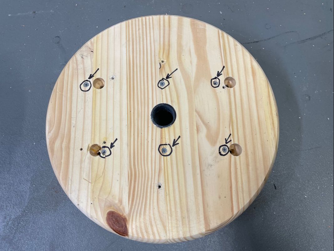
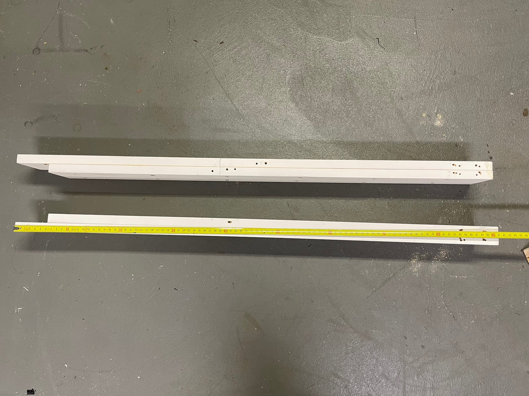
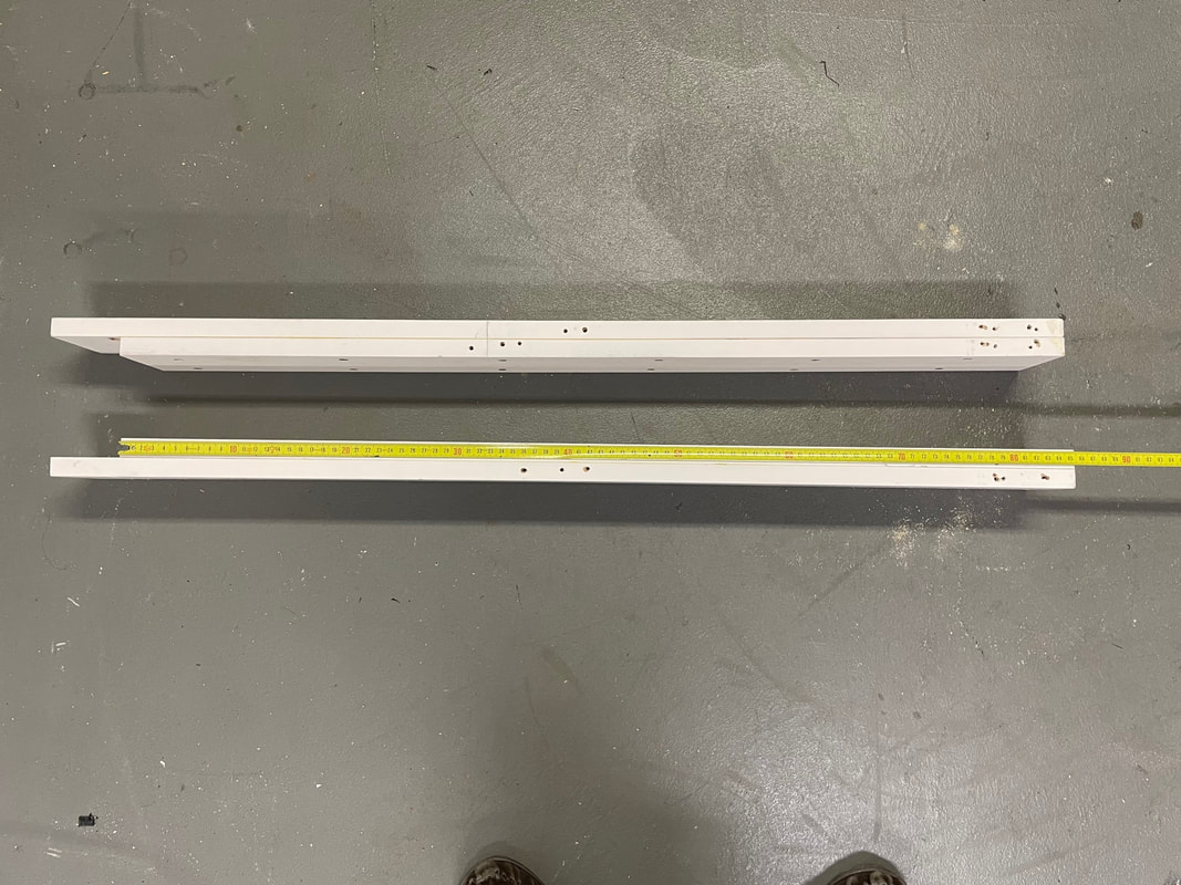
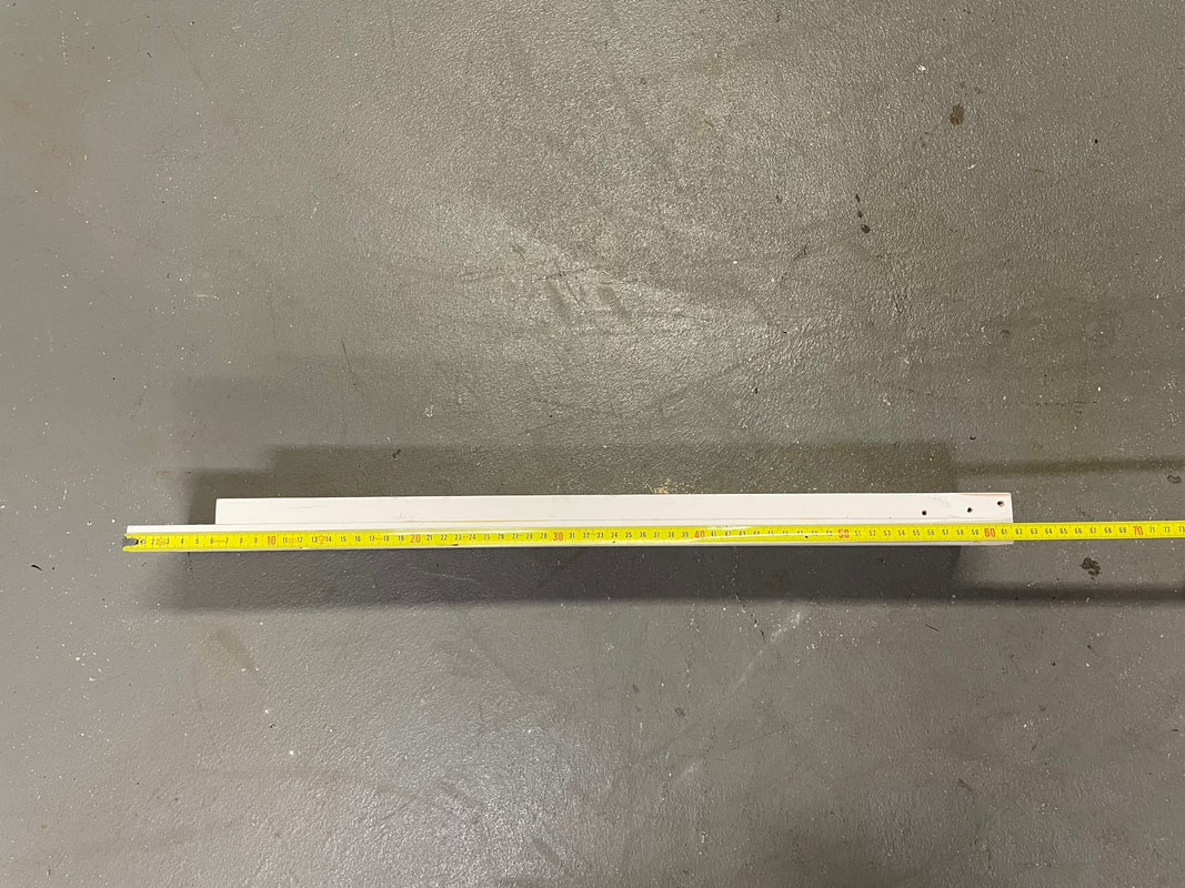
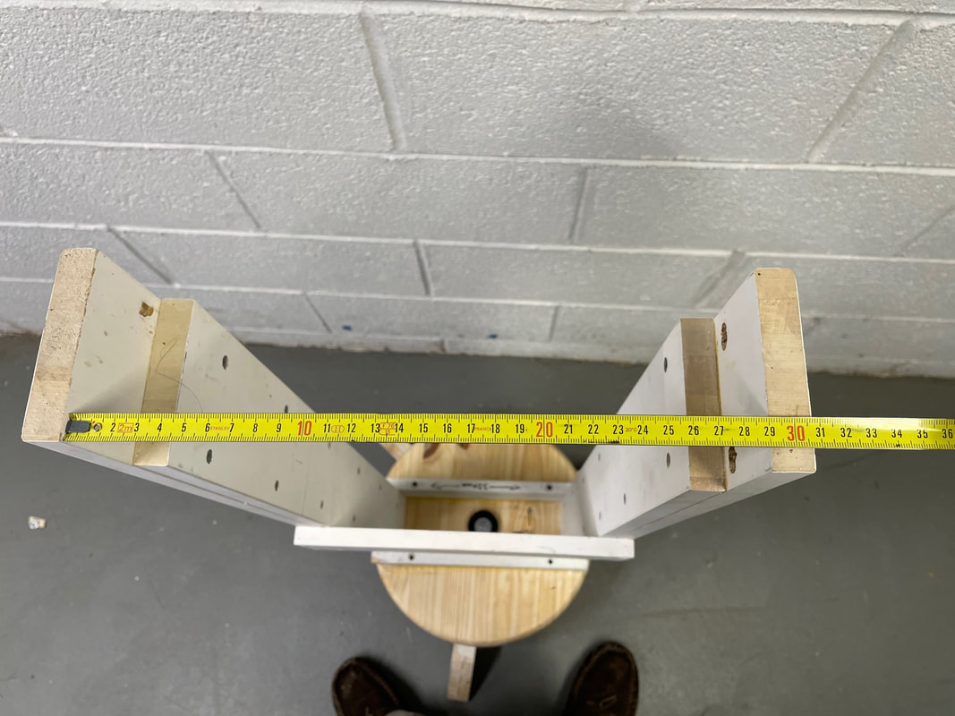
Photo showing length of pieces:
Photo showing the 90mm or 3 1/2 inches of separation between the two pieces:
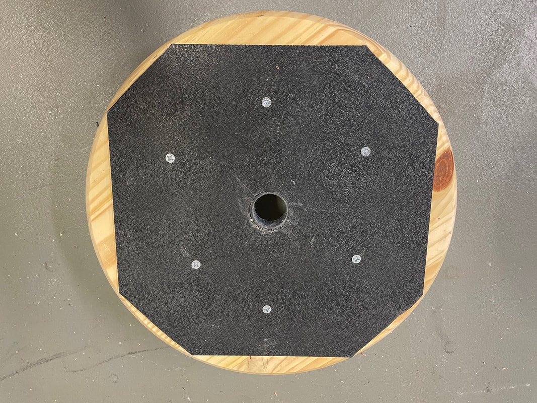
Next screw the ABS sheet to the bottom of the wood disc, making sure that the screws are inside of the circle diameter of the teflon sliders, so that they will not hit the screw heads as the azimuthal bearing is rotated. You also use contact adhesive between the ABS sheet and the wooden disc to make sure it is completely flat over its surface.
Fit the top wooden disc over the axle protruding from the center of the lower disc and check that it can rotate smoothly. Next take the 3D printed part#32, a washer and a 3 1/2" long, 1/4-20 bolt, as shown in the photo, and install them as shown in lower photo:
After you tighten the bolt the upper disc must still rotate smoothly without binding, Make any adjustments if necessary. The base as shown below will be used as the common part for all the following variations in the alt-azm mount. These variations permit the 114mm F8 binoscope to be used by young and old observers by varying the height of the altitude bearing arms as well as permitting an adult to be seated in a comfortable position while observing. It will also be used as a single arm mount for the 150mm F5 binoscope and can be used as a single arm mount for the 80mm F7.5 Refractor binoscope.
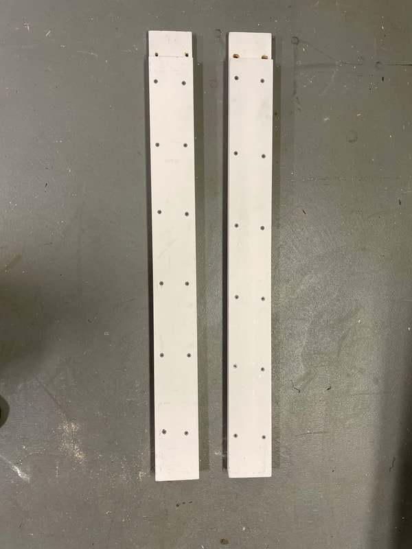
Next we are going to build up two long side arms which provide a comfortable viewing height for people between about 5' 6" and 6'. Cut 2 pieces 914mm long. There is nothing magic about 914mm, If you are really tall then make them 100mm longer. If you want the binoscope a bit lower (but not as low as the child height) then make the pieces 100mm shorter. Once you have decided on the length you need, you are going to cut two further pieces which are 60mm shorter.
Cut two pieces 854mm long assuming that the longer pieces are 914mm. Square up and sand each piece to the correct length using a belt sander.
You are now going to glue (standard wood glue) and screw (using 1 1/4 inch screws) the shorter length to the longer length. Make sure that one end (it will be the bottom end of the altitude arm) is perfectly aligned leaving a gap of 60mm at the top end, this is where the receiver cup (part#24) of the altitude bearing will be located.
Now we are going to cut two lengths of 620mm and two lengths of 560mm and glue and screw them together just like the long ones above. The height of the eyepieces with these shorter arms will be a foot lower than the longer arms and will be suitable for children from about 4' 6" to 5', or crouching or seated adult.
Now take either the long pair of altitude bearing arms or the shorter pair and screw them between the two 320mm pieces on the base of the mount, using 8, 2 inch wood screws, with the longer piece of either pair being on the outside. Do not use any glue.
