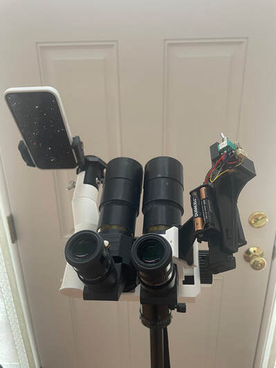
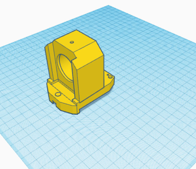
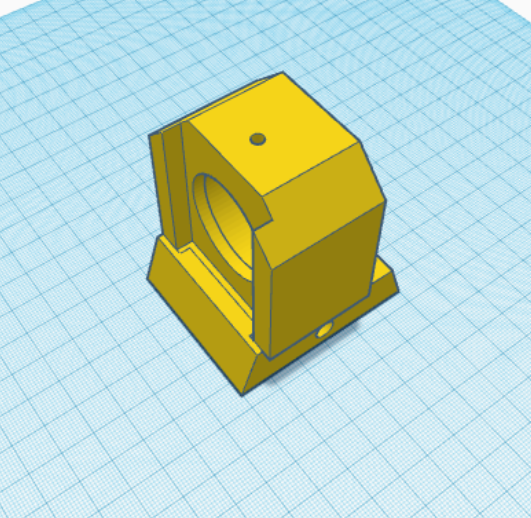
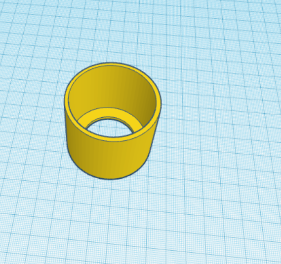
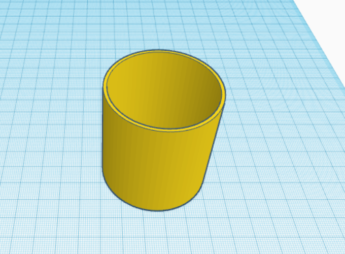
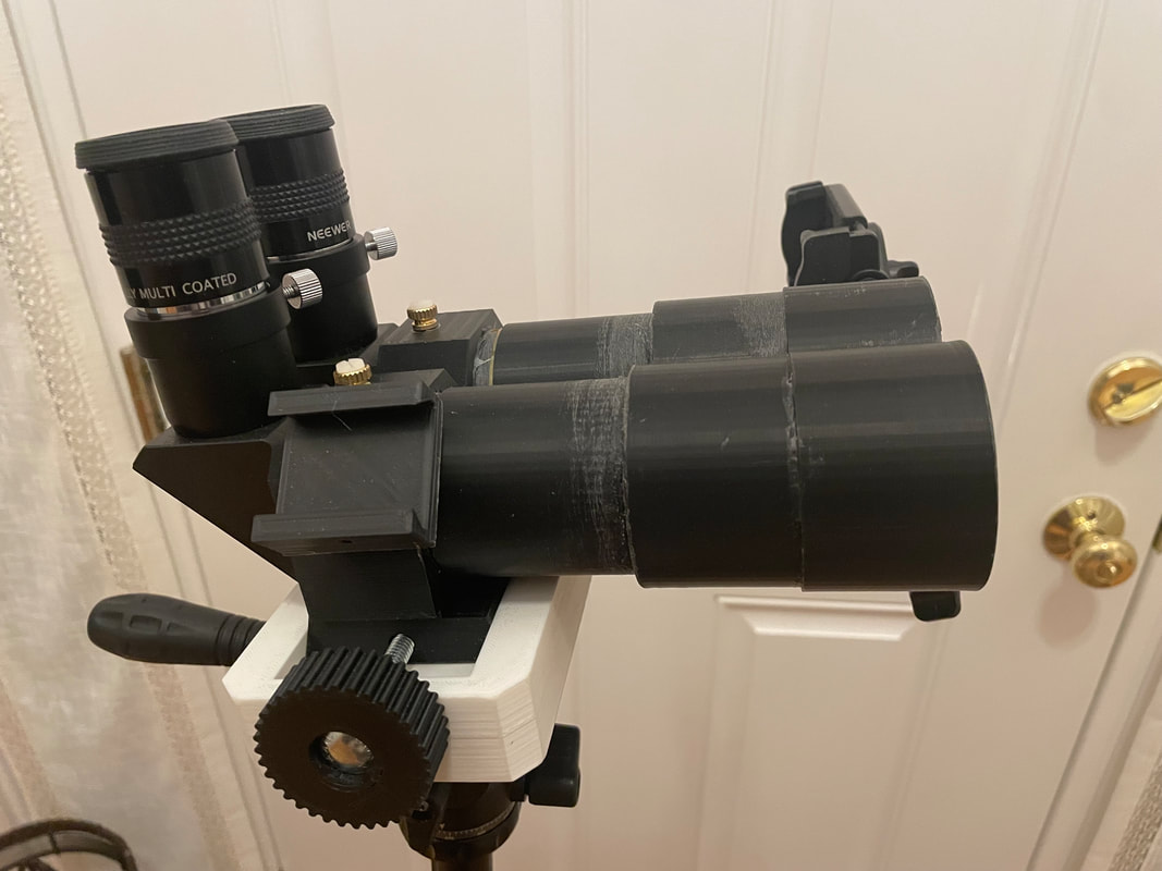
Finding objects in the sky can be one of the most frustrating aspects for amateur astronomers, especially ones starting out on this hobby. This task is becoming ever more difficult as light pollution increases where only second magnitude stars can be seen from many people's backyards. The binoculars shown here are very comfortable to use because of the 90 degree eyepieces, weigh less than 800 grams (28 oz) and enable 7th magnitude stars to be easily seen over a 6.5 degree field of view even in highly light polluted skies. They are much brighter and provide better contrast than the commonly used 9X50 monocular finder attached to many telescopes and as will be seen later they can act as a remote finder for the main telescope or large binoscope nearby. They can be mounted on a photo tripod with a ball head or small video head and it is easy to merge the images while viewing, They provide ~8.4X magnification with inexpensive 25mm plossls, but because it is easy to change the eyepieces to quality 15mm ones with good eye relief they can be comfortably used at 14X. If you mount them on a small video head which provides enhanced stability they can even be used up to 30X with suitable eyepieces to clearly follow the movement of the Galilean moons, see the bands of Jupiter, observe that Saturn has rings, realize that the craters on the moon create sharp shadows and easily split 10 arc second doubles. In other words, support a lifetime of casual observation of the night sky, no telescope needed. However, if you want to see open and globular clusters and distant galaxies in all their glory with a telescope or even better with the 150mm Dual Newtonian Binoscope shown on this website, these binoculars, running at 8X, will help you track down all the wonders of the night sky.
This set up enables a smart phone running a suitable planetarium app to be used as an accurate means to quickly and efficiently find celestial objects in the sky. Many people assume that the smart phone planetarium apps are not accurate because they are not using the right app for the task or they are not mounting the smart phone in the most convenient way, There are so many planetarium apps out there it is important to chose one that has certain essential features, i.e.,
1) The app must display a true photo of the sky showing stars down to at least 7th/8th magnitude, digitized sky maps are confusing and hard to compare to the visual image in the binoculars.
2) The app must have a quick and simple means of applying a compass correction to calibrate the compass (azimuth) on a nearby bright star, ( i.e., one within +/- 30 degrees of the object you are searching for)
3) The app must be able to display approximately a 6 degree field of view which will match the view in the 8X56 binoculars shown here.
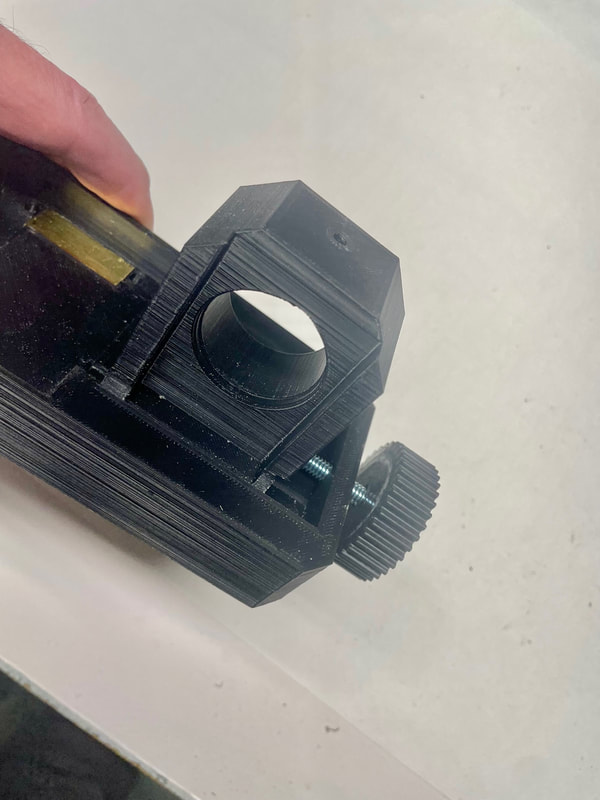
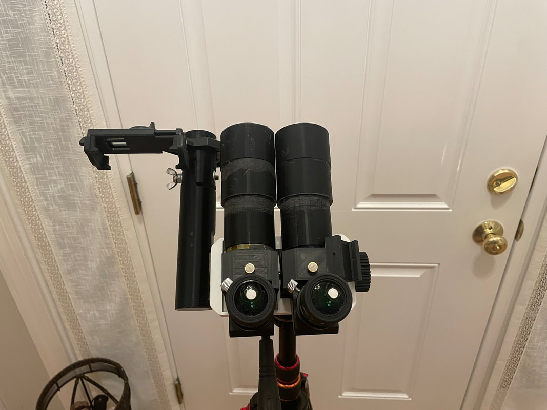
One free app that has all these essential features is Sky Guide which has been created using 37000 stunning photos of the night sky. This app has an easy to apply compass correction by holding your finger on the screen for 2 seconds and then sliding your finger to bring a bright calibration star into the horizontal center of the screen matching the view in the 8X binoculars. To bring the calibration star in to the vertical center of the screen the smart phone mount should be adjustable in the vertical plane over +/- a few degrees (see photo above, the black end of the iphone holder moves up and down 10 vertical degrees and then is fixed with the wing nut)
An important feature of the mount is that it must hold the iphone securely and as high as possible to permit viewing when pointed at the zenith. After calibrating the star image on the smart phone you enter the desired object into the app and follow the guide arrow on the screen. When you are near the object you look back and forth from the screen to the 8X binocular finder until you see the same star field in both. You have effectively positioned the binocular finder on the searched for object using visual plate solving using your eyes and brain. I use a small door on the iphone mount to mask out a circular 6.5 degree field of view on the iphone screen so the image on the iphone will closely match what you see in the 8X binocular eyepieces. Shown below are all the 3D parts you will need to print for the basic unit. One very useful feature if you mount these binoculars on a tripod with a ball head is that there is no "Dobson Hole". This is the region around the zenith which cannot be pointed to with a 2 axis Alt-Azm mount but because the ball head allows movement in a 3rd axis it is easy to point the binoculars to any point at and around the zenith.
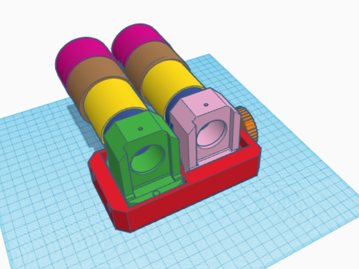
The screen shot above shows all the parts that need to be 3D printed for the basic 90 degree eyepieces, 8X56 Binoculars and if you do not need the enhanced finder capabilities, using an iphone and 4mWatt green laser, these parts are all you will need to print.
Part#1 RED Base
Part#2 GREEN Left Eyepiece holder
Part#3 PINK Right Eyepiece holder
Part#4 BLUE (Print two) First part of OTA
Part#5 YELLOW (Print two) Second piece of OTA
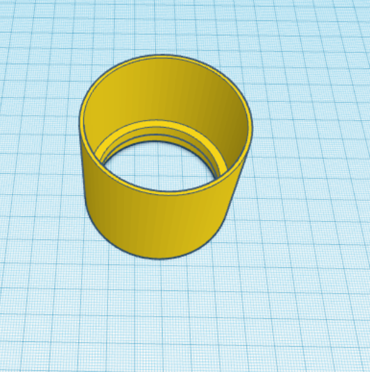
Part#6 BROWN (Print two) Objective holder, third piece of OTA
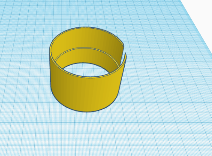
Part#7 DARK PINK (Print two) Objective Clamp, forth piece of OTA
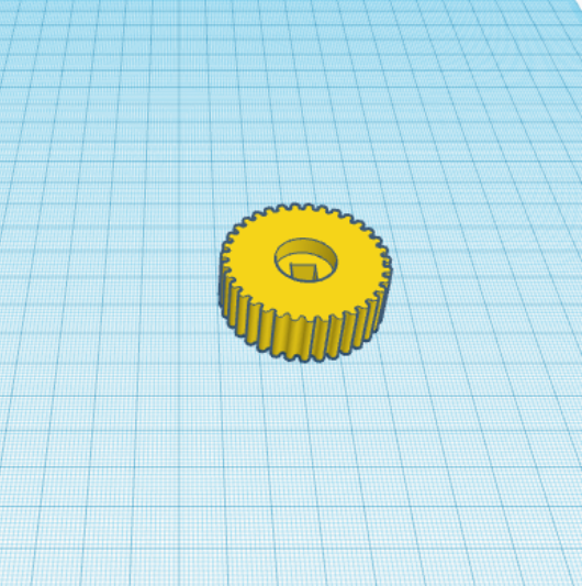
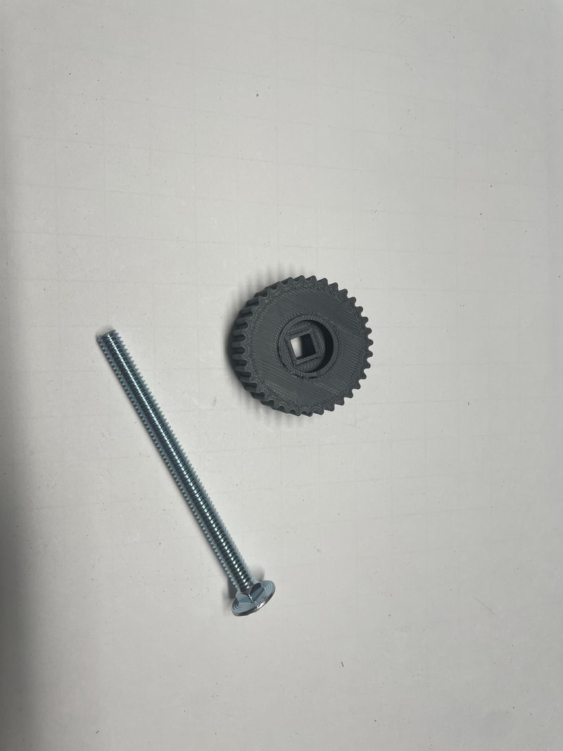
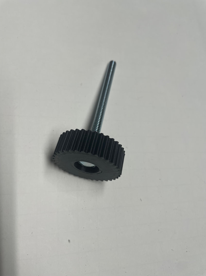
Part#8 ORANGE IPD Adjustment Wheel
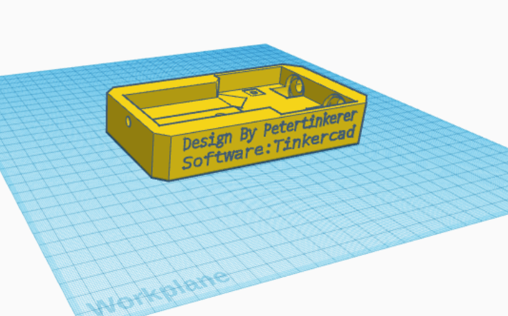
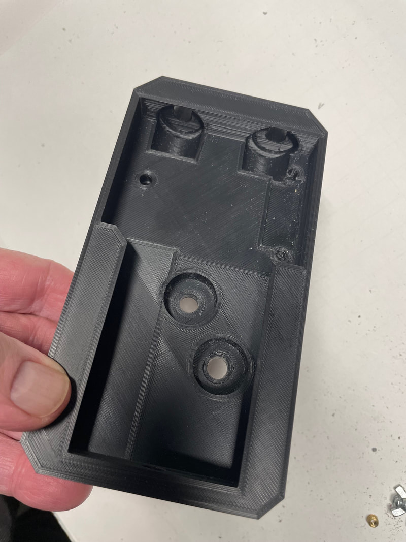
The base shown below should be the first part to be printed (Part#1)
Here is the .stl file. You will need to download it and run it through your slicing program (I use Cura) to create the gcode for your specific printer or contact me at , [email protected] and I may be able to print it for you. . I print with 10% fill at standard quality (0.2mm layers) with ABS filament, and on a Creality CR-10 it takes about 10 hours to print.
| 56mm_part_1b.stl | |
| File Size: | 499 kb |
| File Type: | stl |
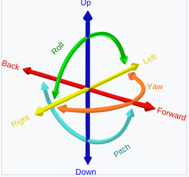
Next, 3D print the left objective holder (Part#2). This part appears to be simple since it looks as if it just holds the left eyepiece but it is much more subtle than that because it needs to be capable of 4 degrees of freedom. If we define as Forward the direction of observation then Part#2 has the ability to adjust roll, yaw, pitch and up-down all accomplished by adjustements of its 3 point mounting. We will see that Roll, Yaw and Up-Down are calibrated and then remain fixed whereas Pitch, which effects the vertical merging of the two images, is a setting that is so sensitive it is essential that it is adjustable while viewing.
Here is the .stl file:
| 56mm_part2b.stl | |
| File Size: | 278 kb |
| File Type: | stl |
Next print the right, movable, objective holder, Part#3, which coves the Left/Right degrees of freedom and enables the IPD to be adjusted from 58mm to 75mm. Make sure that you select "support"- "touching base plate" option in the slicing program. If a narrower IPD is needed the 58mm objectives are replaced with 51mm objectives which permits the minimum IPD to be reduced to 51mm. This will be described in the options section later.
| 56mm_part_3b.stl | |
| File Size: | 116 kb |
| File Type: | stl |
Next print the first part of the optical tube Part#4. You print two of these pieces:
| 56mm_part_4b.stl | |
| File Size: | 38 kb |
| File Type: | stl |
Next print the second part of optical tube Part#5 You print two of these pieces
| 56mm_part_5b.stl | |
| File Size: | 25 kb |
| File Type: | stl |
Next print the Objective holder Part#6. Use the setting "support" "Touching Build Plate". Print two of these pieces.
| 56mm_part_6b.stl | |
| File Size: | 51 kb |
| File Type: | stl |
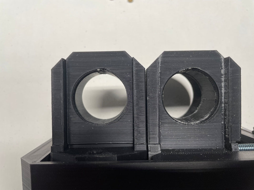
Next print the objective locking pieces Part#7 Print two of these pieces. The cut out on the side is to permit the IPD range to extend down to 58mm, which is the actual diameter of the objective lenses. The small section of the lens which shows through the gap is blackened to avoid any light entry.
| 56mm_part_7b.stl | |
| File Size: | 37 kb |
| File Type: | stl |
Next print the IPD adjustment wheel Part#8
| ccr10_56mm_part_8b.gcode | |
| File Size: | 6153 kb |
| File Type: | gcode |
Let us start to assemble Part#1 of the binoculars:
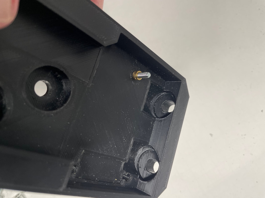
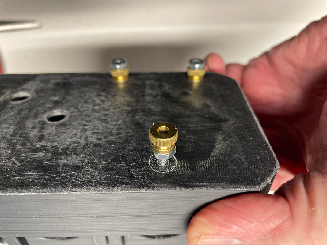
Next install the 6-32 brass insert. The hole size is a friction fit and you do not have to use heat to install the insert. Just use a 6-32 bolt to pull the insert into the hole. There is an orientation to the insert , make sure you pull in the narrower end first.
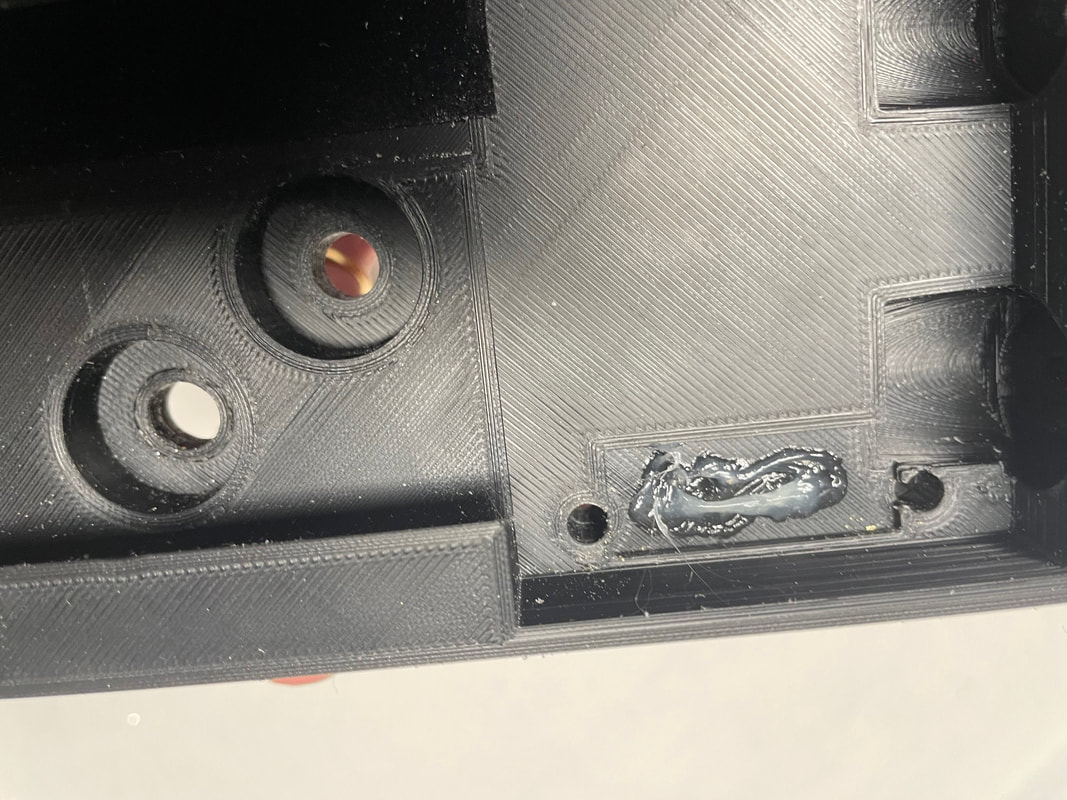
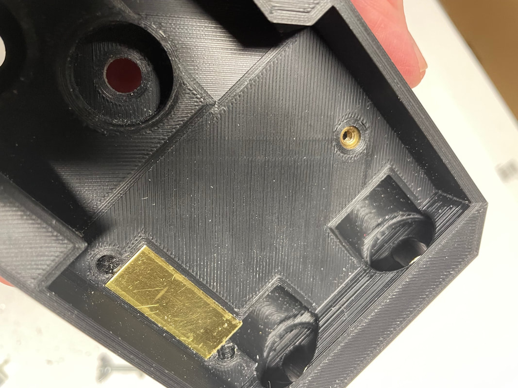
Next glue in the 10mm by 30mm brass plate
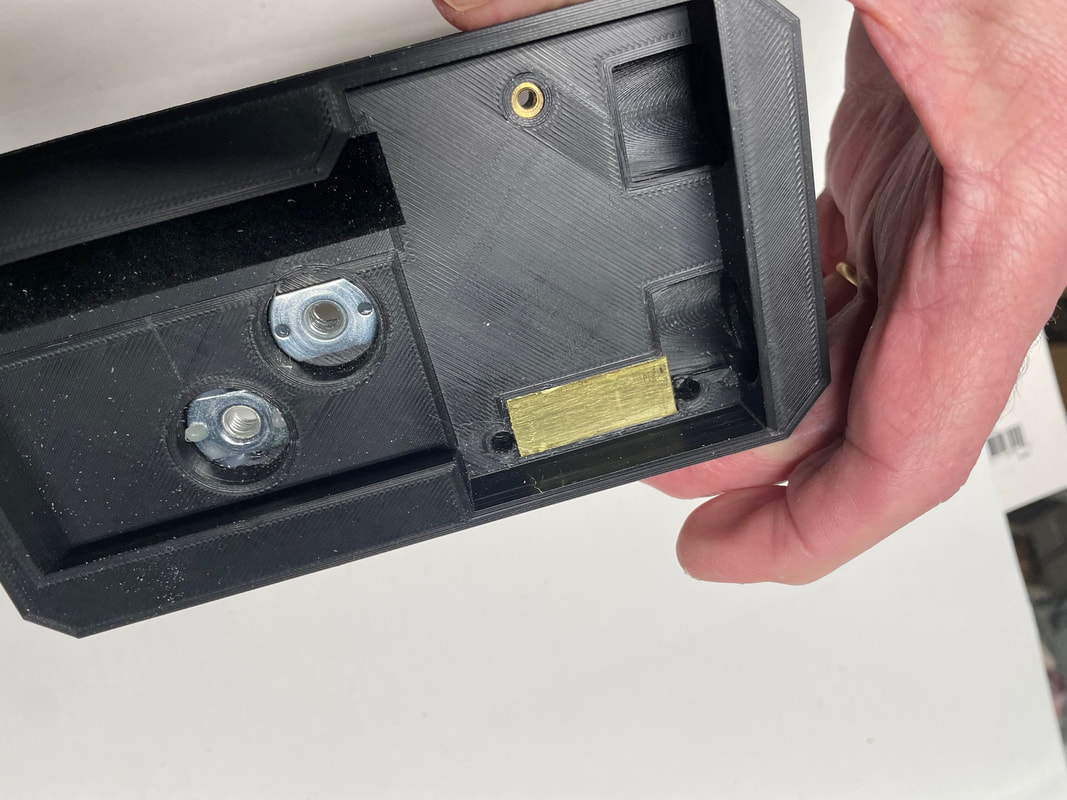
Next glue in the two T nuts which are for attaching the mounting plate of the tripod head in one of two positions. Attach the strip of black flocking as shown which takes up any play in the sliding movement of Part#2.
Next glue in the 3 1/2 inch carriage bolt into part#8 using Devcon two part plastic epoxy:
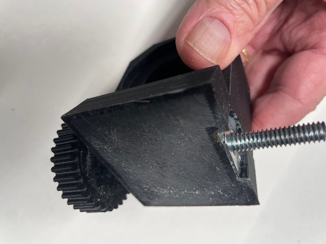
Next glue in the 1/4-20 T nut into part#3 and use the IPD adjustment bolt to pull the T nut into place:
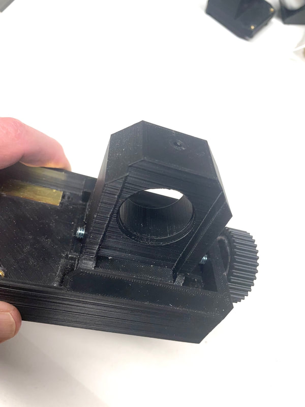
Unscrew the IPD adjustment bolt and install Part#3 i into the sliding section of the base, Part#1, Install the IPD adjustment bolt:
To increase the IPD turn the IPD adjutment wheel in a clockwise direction. To decease the IPD rotate the IPD adjutment wheel in the anti-clockwise direction and then, using two hands push on the IPD adjustment wheel and the other end of the base and move Part#3 back along the slide.
Now we are going to assemble Part#2. This part is the key part to making the binoculars work correctly and it has 4 degrees of freedom, 3 of which are calibrated and fixed and one, (Pitch), which is adjustable while viewing to vertically merge the two images.
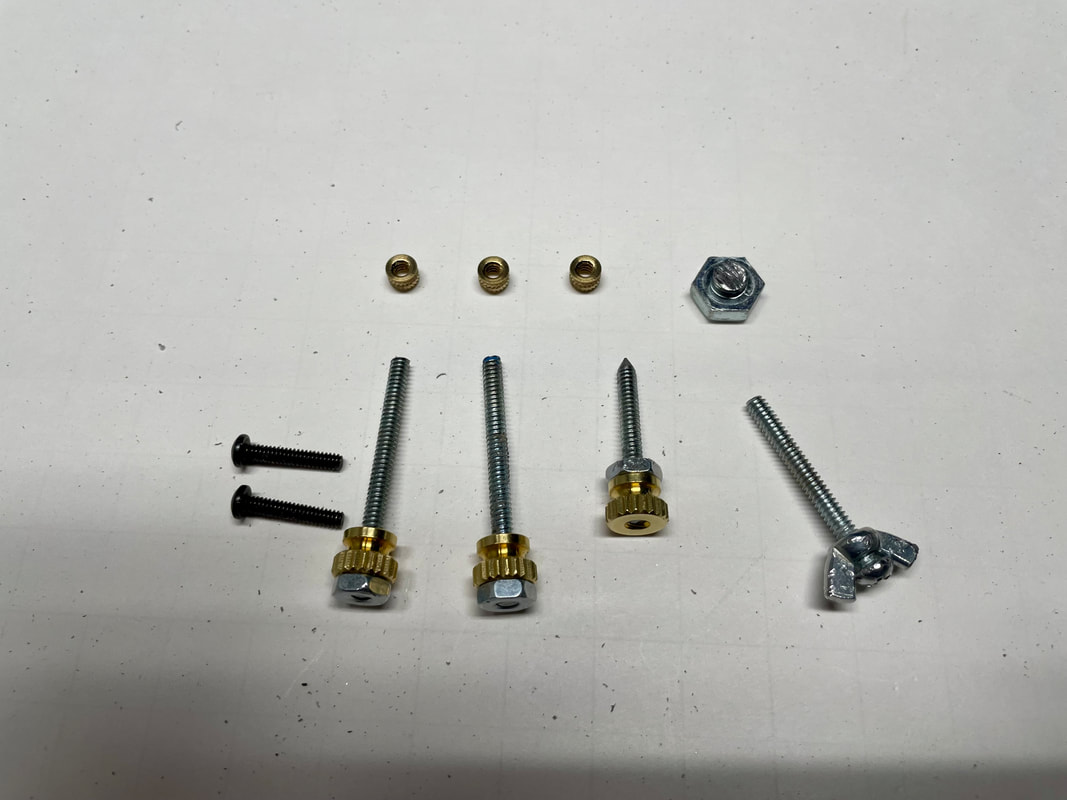
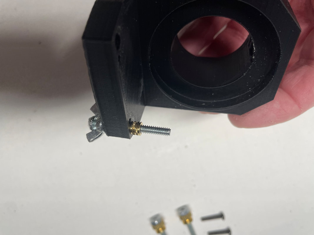
Shown below are the hardware bits and pieces that you will need: 3 6-32 brass inserts, 1 head from a hex 1/4-20 bolt, 2 4-40 bolts (half inch long), 2 pieces of 6-32 threaded rod 40mm long with brass thumb nuts and locking 6-32 nuts, 1 sharpened 6-32 threaded rod 25mm long with brass thumb nut and 6-32 nut. The 6-32 bolt with the glued on wing nut is used for "pulling in" the brass inserts, it is not used in the final assembly.
Shown below are the hardware bits and pieces that you will need: 3 6-32 brass inserts, 1 head from a hex 1/4-20 bolt, 2 4-40 bolts (half inch long), 2 pieces of 6-32 threaded rod 40mm long with brass thumb nuts and locking 6-32 nuts, 1 sharpened 6-32 threaded rod 25mm long with brass thumb nut and 6-32 nut. The 6-32 bolt with the glued on wing nut is used for "pulling in" the brass inserts, it is not used in the final assembly.
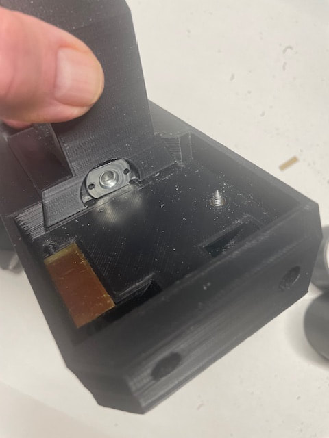
Shown below is the glued on brass plate and the vertical merge adjusting screw which forms the rear point of the 3 point mount and also adjusts the PITCH of Part#2. The brass plate creates a stable platform for the two front 4-40 bolts which form the front two points of the 3 point mount of Part#2
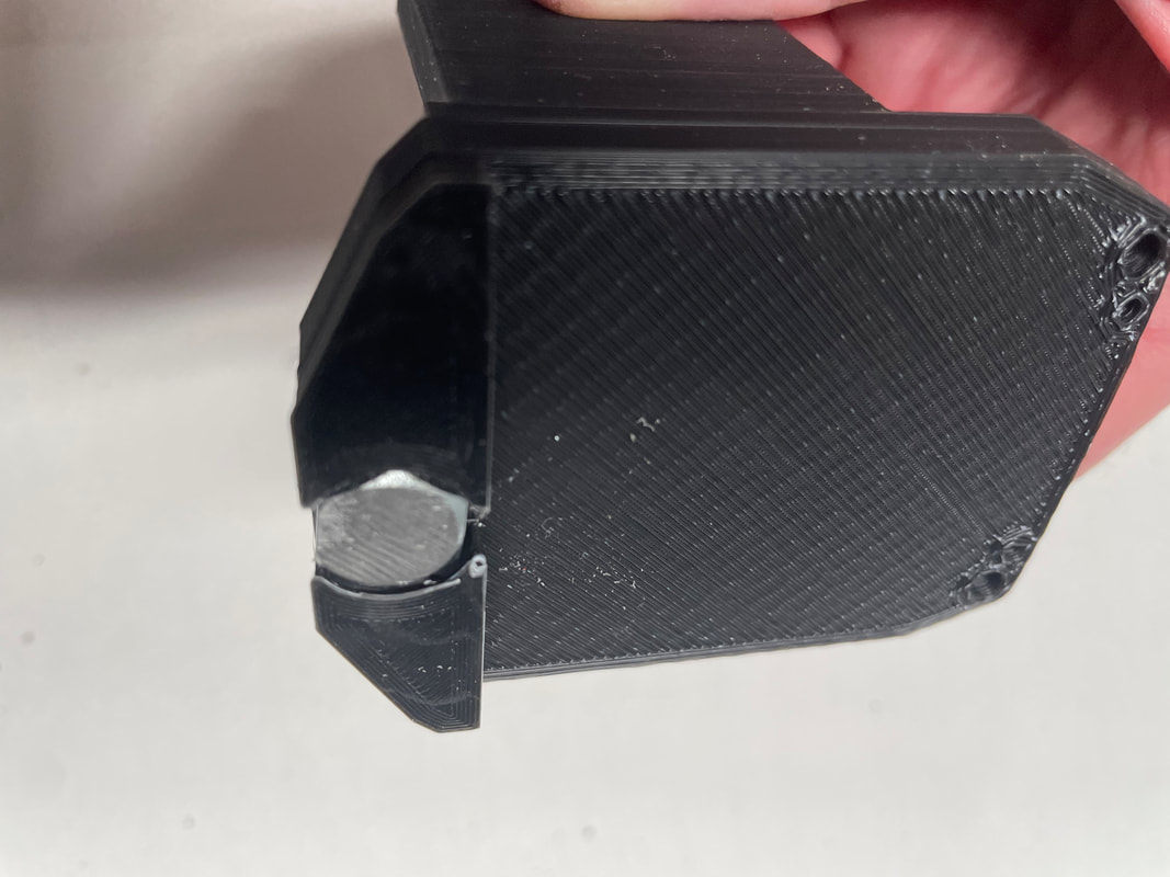
Glue in the 1/4-20 Hex head to the bottom of part#2 after first filing it flat to remove any lettering which is often on the head. The smooth surface of the hex head acts as the bearing surface for the adjustable vertical merge screw and permits Part#2 to move in YAW to calibrate the horizontal merge of the two images.
Next install the two 6-32 brass inserts into Part#2
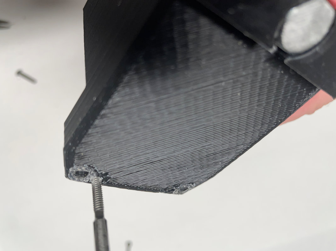
Next tap 4-40 threads into the two small holes next to the brass inserts. You only need to create thread depths of about 3mm just enough to start screwing in the 4-40 bolts. The bolts will create their own threads for the rest of the dept which keeps then tight.
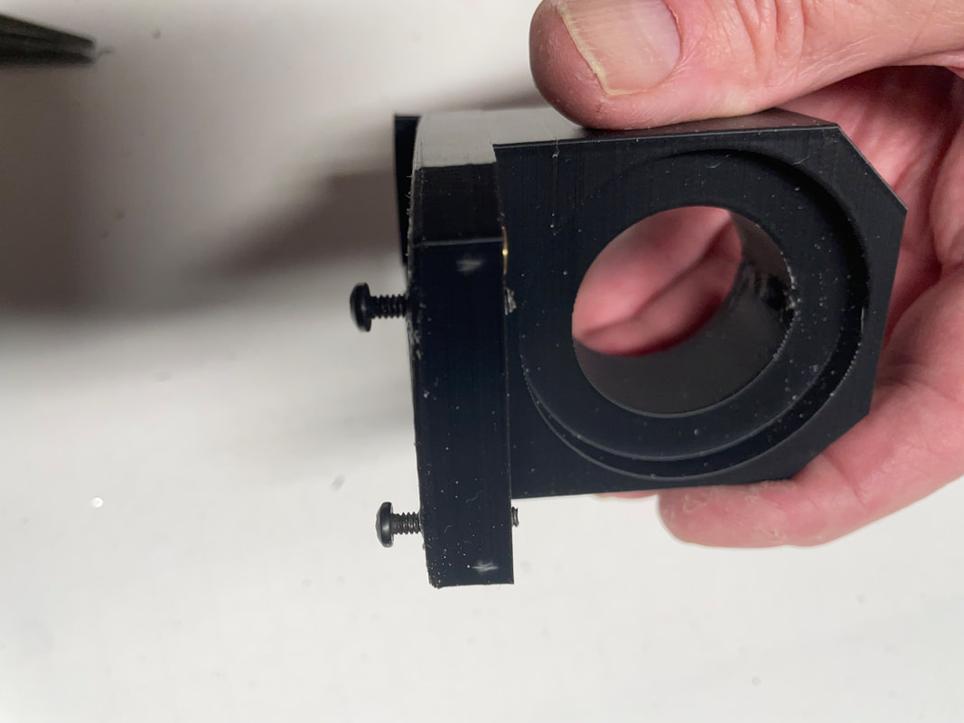
Screw in the two 4-40 bolts as shown until about 1mm extends from the top surface. The adjustment of these two 4-40 bolts will effect the ROLL and UP-DOWN settings of Part$2 and the final calibrations will be done later.
Now attach Part#2 to the base using the two locking screws. Before doing this undo the PITCH adjustment screw so that its point does not protrude above the bottom surface of the base (Pat#1)
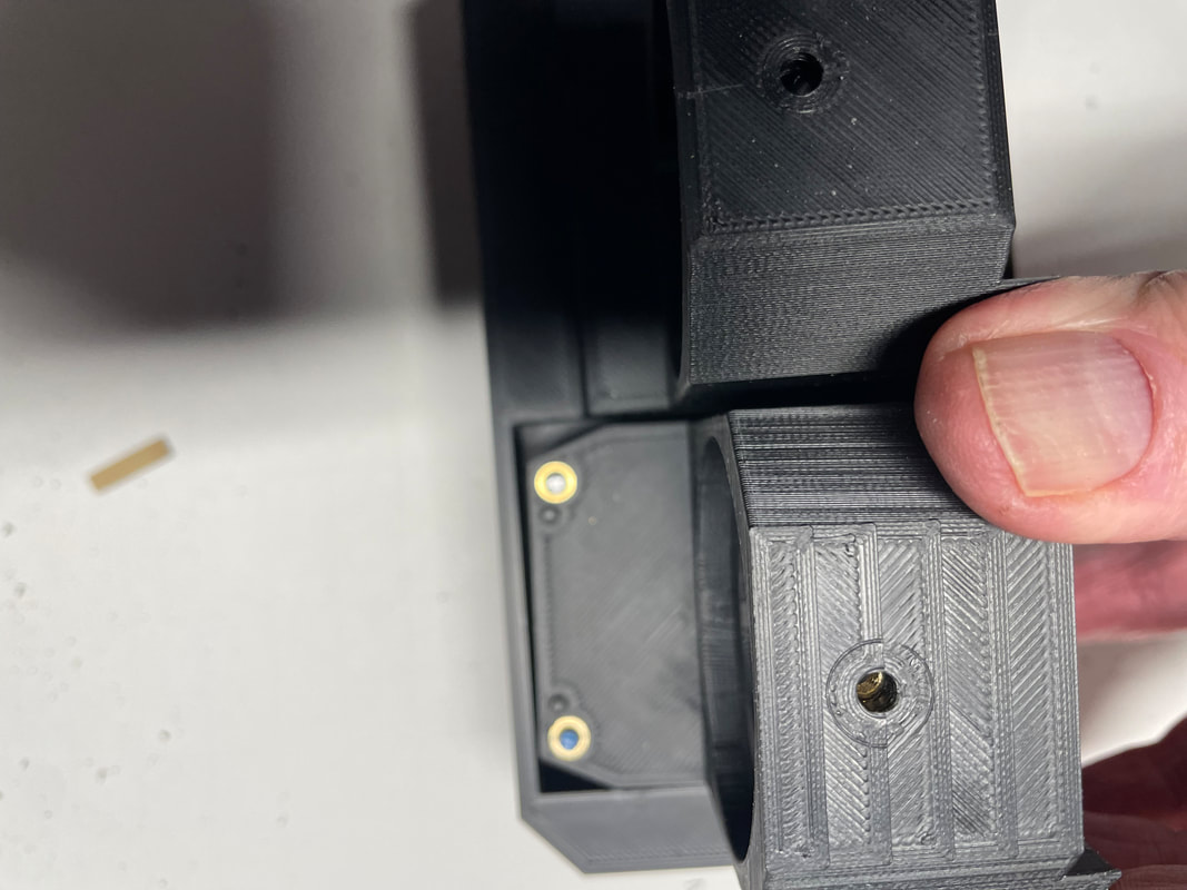
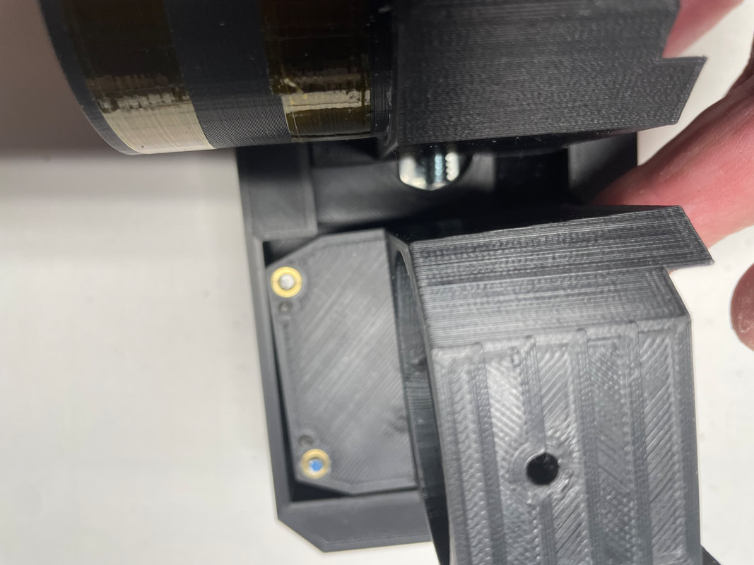
With the two locking bolts loose, Part#2 can be moved in YAW. Look at the gap between the front of Part#2 and the frame (Part#1) in the next two photos. By making this adjustment and then locking Part#2 by tightening the locking screws calibrates the horizontal merge of the two images.
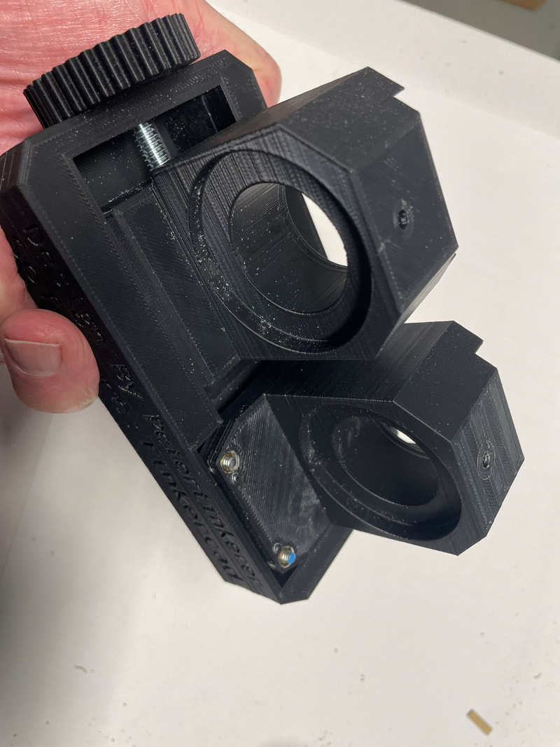
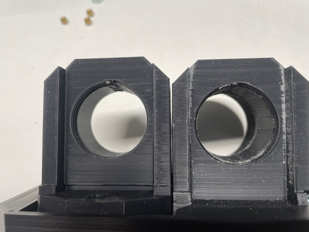
Adjust and lock YAW so that the front edge of Part#2 is parallel to the front edge of the base. Now adjust the PITCH screw to make Part#2 match the vertical angle of Part#3 and see if the edges are parallel. The photo below shows that Part#2 is high and not parallel to Part#3. Remove Part#2 and screw in the left 4-40 screw one turn and the right 4-40 half a turn. This will lower Part#2 and ROTATE it in a clockwise direction. See second photo below:
Now you can see Part#2 it is much closer at matching Part#3. I think you are getting the idea now and a bit further adjustment of the 4-40 bolts will make the match even better.
Now we move on and install the Optical Tube Assemblies (OTAs):
